When [Pete Juliano] sat down to design a sideband transceiver for the 20 Meter (14 MHz) ham radio band, he eschewed the popular circuits that make up so many designs. He forged ahead, building a novel design that he calls Pete’s Simple Seven SSB Transceiver, or PSSST for short.
What makes the PSSST so simple is not only its construction, but the low component count. The same circuit using four 2N2222A’s is used on both transmit and receive. On transmit, an extra three components step in to amplify the microphone input and build output power, which is 2.5-4 Watts, depending on the final output transistor used. The best part is that all of the transistors can be had for under $10 USD! [Pete] shows where radio components such as the RF mixers and the crystal filter can be purchased, saving a new constructor a lot of headaches. The VFO and IF frequencies are both provided by the venerable si5351a with an Arduino at the helm.
Many simple transceivers are designed to demonstrate a minimum viable radio, with performance not really a goal. On the other hand, the PSSST was modeled stage-by-stage in LTSpice, ensuring great transmit audio and nice receiver performance. Be sure to check out the demonstration below the break!
[Pete] has painstakingly documented the entire project on his website, and the code for the VFO is available by request via email. We appreciate this contribution to the homebrew ham radio community, and we’re sure this will provide many nights of solder smoking enjoyment for radio amateurs around the world.
Thanks to [Nick, G8INE] for the Tip!


Including an Arduino and a Lm380 I think there are a lot more than 7 transistors.
He had me in the first half, I must admit.
Your also forgetting the SI5351. I am sure there are 10’s of transistors in there.
Thats what i thought. It is NOT a simple radio only a section of a complex one.
Pete’s radios are frequently worth building. He designs nice, easy to understand and use little rigs.
means “I can’t find the BoM….”
an ssb receiver without a working agc circuit is painful to listen to.
So add another 10 components and have AGC, its really not rocket surgery. Some of us actually do not have broken hands and know how to ride the volume knob for that loud station.
You know, that’s nice and all. RF design is really cool and black magic, but I would really wish it was more accessible.
Yes, I know that this construction style on copper board is super stable and amateurs have done this since who-know-when. And I know its cool to fling around your call sign. And spending time on website design shows you are superficial.
But what the heck. Everything of this reeks of old and dusty stuff from a past generation.
This is cool technology, why not try to make it more accessible?
berb, I’d be intrigued to know how you think it isn’t accessible.
Its a good sound basic design built in a way that’s very easy to reproduce, fault on and modify using easily obtained components. Because Pete has taken the time to engineer it, its simplicity belies it being really quite sophisticated in terms of only using what is necessary, and no more, the mark of a good competent engineer.
The joy of Pete’s designs is that a) he’s spent a lot of time making sure that it does work, b) designs in simple easily understood, built, and tested modules, c) his designs make it easy to use them as a platform to experiment, and d) he is usually accessible to help people who build it and find that they don’t understand something.
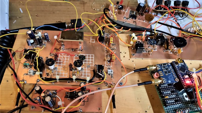
The construction style is easily reproducible using MeSquares, a scriber, a Dremel, a CNC, or just by cutting up off -cuts into pads, so it’s cheap, flexible and accessible to many. The same circuits can very easily be adapted to being reproduced on perfboard, or simply by drilling plain pcb. You could actually reproduce it by driving tacks into a breadboard – oh wait, that old technology …
Far from being “superficial” Pete has been a very prolific designer and has made his work open and available for anyone to pick up and build themselves. Getting on for 100 people have picked up his design for a Direct Conversion receiver from last year, some of them engaging in amateur radio for the first time.
I look forward to Hackaday carrying project from you that demonstrates the use of “cool technology” and that is more accessible.
hear, hear!
Maybe it’s the part about requiring soldering that makes it so inaccessible. Or “welding” as I’ve heard it called, by people who think that every electronic module should have holes you just push wires into. I don’t know what they do when they can’t find pre-cut and stripped jumper wires.
Now I’m off to chastise flight sim players who call themselves “pilots”.
In some languages there’s just one verb for both soldering and welding. I’ve accidentally called it welding many times, even though I’ve been soldering for 35 years.
I didn’t mean to make fun of people whose first language isn’t English. But this wasn’t a language thing. Here was the situation: having been a technician for over thirty years, I had decided to get a degree so I would have Engineer credentials. In one of the labs, my project was too complex to fit on a breadboard, so I had wired up a portion of it in deadbug fashion, with the chips pins up on a piece of copper-clad board, with interconnecting wires soldered directly to the pins. As you do, if you don’t have time to order a PCB. I had to make a change to this part of the project, so I checked out a soldering iron and made the modification. At this point, one of the other guys in my class – this was a fourth-year electronics class, so he was just a few months from going on the job market as an electronics engineer – said, “what’s that you’re doing? Are you welding that?”
This was over twenty years ago, and it’s just gotten worse since then. I saw a comment on a YouTube video about the Raspberry Pi Pico board, where the person was saying he wished the board came with headers already installed. Come on, folks, if you want to do electronics, learn some of the physical skills. Would you call yourself a painter if you didn’t know what the stick with the little wad of hair on the end of it was for? Would you want to learn how to cook without ever heating up a skillet?
:-), ;-) :-) 73 Ron AC7AC
Well said Nick, some of us actually know a good design when we see it and others just like to pontificate on the internet to show others how leet they are.
Pete has a proven track record of many decades of dedication to the art of ham radio home brew and has built more radios that most people. He gets my respect.
I could see where people who are used to more PCB-oriented designs would find this style of construction unfamiliar and intimidating.
The grid-board setup might be good for prototyping and experimentation, but if you’re more interested in building it as-is, then it presents some drawbacks: loose wires and multiple modules floating around makes it more subject to physical damage from mishandling and unexpected shorts. From a “looking at the layout to understand the circuit” perspective, it’s sort of an unfamiliar “encoding” of the data.
It would be interesting to take a stable snapshot of the schematic and render it as a PCB… I suspect that would be a lot more comfortable for some builders, and it could still be engineered in a way to support the admirable “build and test individual subsections” approach.
Wait until people find out that they have to have a HAM license to use this thing. :P
And how difficult that is, what with the Morse Code test … never mind.
Actually they got rid of the Morse code requirement for the US and it is ~35 multiple choice test about the law, basic operation procedures and some basic electrical theory.
OP has a bit of accessibility about “RF design”…
Well you got to know enough of it to pass the test. Buying shit doesn’t help you there.
Okay, here’s the thing: there used to be a Morse Code test (although not for Technician Class), years ago, which was the hard part for many people. The ellipses indicate a pause, as I was realizing that with the elimination of the code test, there was nothing difficult left, thus the “never mind”. Are you saying that even with such a detailed structure, I STILL have to include a :) in order to not be taken literally?
At the end, I was told by a test taker that the Morse test consisted of a form with the test message already printed upon it. Every second word had a missing letter that you had to fill in, 60% correctly. He also said that he and 3 others out of 20 were the only ones that passed the test. When I took my test years before, 5 minutes receive without error, send with one error per minute if you corrected it using the error character followed by the correct character. I remember there being 12 of us with only one failing. He corrected his last sending error but forgot the error character. Between my test taking and the last round of Morse testing, the easier it got the higher the failure rate. Seems the same with magazine construction articles, the easier the projects become the more people bitch about the extreme difficulty. I’m waiting for someone to complain about the unreasonable expectation of having to connect an otherwise fully constructed “kit” to a power supply.
Using a universal breadboard etched pcb is about the most direct way from schematic to built circuit. Laying out pcbs with tiny rolls of layout tape and an xacto knife wasn’t much fun. Now there is many cad programs and board houses to make your design really cheap. For a one off dead bug works. Remember things like the ugly weekender in QST? Roy Lewellen and Doug Demaw had it going on with circuits without a pcb.
I might go so far as to say that I can sometimes get a cleaner layout with deadbugging than laying out a PCB. With the deadbugging, I don’t run out of layers. I’ve never used PCB layout tools for RF stuff, though, so I’m just spouting my prejudices here. I mean, I HAVE routed high frequency designs on PCBs; I just haven’t done any “RF” work there. Mainly because my RF work has ALL been one-offs.
What’s most ‘accessible’ is to just buy the latest pre-built Japanese transceiver with a 200 page instruction manual for $10,000 and plug it in to power and coax. Is that what Hackaday is about? Nope. It’s about originality, about circumventing the typical consumer products to do something cool. “Old and dusty?” Electromagnetic physics doesn’t change that fast, in fact, hardly at all over decades. This is a great, functional design with which to learn RF by building something with easy to understand circuitry, not a bunch of black boxes. It has good performance, is high-tech digital where high-tech digital makes sense, and traditional analog where traditional analog makes sense. It has easy to use, very common, inexpensive parts, and even more importantly, it’s something a ham can learn on and also have a good expectation that it will work effectively when they’re done, because it uses the right parts, and parts that are large enough to actually see. That seems like the perfect combination of sophistication, simplicity, and price to me.
I think that’s what Hackaday should be all about when it comes to ham radio projects. We aren’t CB’ers. Understanding radio is a key aspect of the hobby. So, after I’ve spent the last 2 weeks looking all over the web at other HF SSB transceiver kits and projects I’m going to build this very rig so I can become a more knowledgeable and proficient ham, and for very little money have a good performing little HF rig when I’m done. Folks who just want to be appliance operators, or cut a trace and wire in some little module to add a feature are welcome to do that. And people who want to plug together a series of expensive blackbox digital modules and think they are then knowledgeable about RF can do that, too. Good for them. For me, this is an ideal Hackaday project. I don’t know the designer, but I’ve carefully reviewed his design to the best of my ability, and watched the video of the rig on the air, so I know he’s a no-nonsense, experienced radio designer who considers all the variables as he designs. That’s a lot of work, and it requires a lot of knowledge, so I would like to thank him for a well engineered, carefully thought-out project that’s about the best thing I’ve seen on Hackaday since the start of the pandemic. And he didn’t charge a penny for it. He’s the very definition of a great Elmer. – John
Thanks for the laundry list of what things YOU like, and therefore Hackaday should be about. Some of your points may be valid, but for every person wanting parts “that are large enough to actually see”, there are several people who are happy to use a microscope if necessary to make something cool. For every “I want to use nothing but transistors, inductors, capacitors, transformers, and resistors”, there’s another who wants to be able to play with their modulation and demodulation in software.
You know what’s great about amateur radio? If there are a million hams, there are a million ways to enjoy experimenting with RF communications. ALL OF THESE ARE VALID.
Ham has been gatekept into oblivion. Every time some old Ham dies and radios go on sale so that maybe us younger folks can finally afford to get on the air with something other than a UV5R, what happens? Every old coot in the hemisphere swarms like vultures and adds the radio equipment to their ever increasing horde. Oh you wanna learn on a real radio? Join our club full of old racists and dudes that like to feel up on any woman you might try to bring into the hobby. Maybe it’s just where I’m at (appalachia) but it is ridiculously bad. I got my license and a barely use it bc there frankly ain’t no one worth talking to in VHF range.
That said these replies are full of holier than thou examples of the type of vitriolic bs I’m talkin about. Ham isn’t easy to get into bc it’s being gatekept by a bunch of Neolithic codgers hell bent on not letting anyone in unless they get in “the right way”. It’s embarrassing.
That said again, maybe it’s not everywhere, but it is a lot of where.
That said this is actually an example to get out of that pit. The whole reason I became an electronic hobbyist was to be able tonafford to make my own radios because God knows I’ll never get my hands on an icom or yaesu.
great idea. I need 2 device with Raspberry pi hat and extended antenas ;-)
Nick –
Spot on. Our club just completed a group build of Pete’s SimpleSSB – a predecessor to the Pssst! What makes it great and accessible is the modular design. You build a module and test it. Build the next one and use the prior module to test that one and before you know it – bang – you are on the air with a scratch build transceiver. Not a kit, not a credit card special – a true homebrew rig that you built yourself. We had 15 builders who had never built anything before work on this project and all of the receivers are on the air and most of the complete transceivers. We are making phone and digital contacts all around the world on Pete’s design. There is nothing quite like the feeling you get from operating a transceiver that you have built yourself.
The use of the microcontroller and SI-5351 is part of what makes this accessible for first time builders. Pete has taken the risk out of building a transceiver this way. The beauty of the modular design is that if you don’t like one of Pete’s modules you can swap it out for one you like better – or better still get out your pencil and design your own circuit to replace it. You want an AGC – build it in. Color touch screen, have at it. Heck if you really don’t want to use the old, crusty Arduino and SI-5351 go ahead and substitute your favorite analog VFO. In my case after completing my rig extended Pete’s design with an audio derived AGC and S-Meter. I added CAT control to the firmware and made it a multi-band 20/40 meter transceiver and added a color touch screen display. A modular design like this becomes an experimenter’s platform.
Bottom line Hackaday readers if you want to learn about building superheterodyne HF radios there is no better place to begin than with an N6QW rig. My advice is to build one of Pete’s designs, get it working and then start experimenting.
Thanks again Pete for another great project!
73,
Dean
KK4DAS
Verbatim from the video:
“Seven transistors. Four being used on the receive function here, six being used on transmit.”
Yes, I do realize that some transistors are used for both modes. It was just hilarious to hear.
I’m not sure what the point of the “under $10” claim is, when that is for just the transistors. Typically, aside from any RF power transistors, the transistors only contribute less than $1 to the BOM, and that seems to be the case here. But once you add the commercial crystal filter, two Si5351 oscillators, and a T/R switch or relay, the cost of transistors becomes insignificant. Might as well boast that it only needs $0.05 worth of solder.
Oh, right – and the Arduino to control the oscillators, and the speaker amplifier. Missed those.
Excluding the micro controller, the rest of the radio can be built for under $10, its not hard to home brew the xtal filter and the mixers, the most expensive component would be the relays @ 50 cents each same as the final transistor in the PA.
Well, AVR boards go for around $2 on Aliexpress these days. Sure, you want to support the developers – but if we’re counting cents and trying to save money here, there’s no shame in buying your open-source hardware from China.
I would argue that for a beginner, and that’s who this is aimed at, homebrewing the crystal filter so it performs as you expect IS hard. Also, you’re showing your age with the 50 cent relays.
https://lcsc.com/products/Signal-Relays_11305.html
Yeah i over quoted, signal relays in 1 off quantities are only 40 cents and get cheaper with quantity.
Just for fun, I tried ordering five of these. The cheapest shipping was $6, for a total of $1.53 per relay. Still cheaper than I expected, but not $0.50. If you’re going to quote overseas parts, it is disingenious to leave out the shipping.
An old saying we have out West:
https://idioms.thefreedictionary.com/you%27d+complain+if+you+were+hung+with+a+new+rope
Some people would complain even if we hung them with a new rope :-) I see a lot of that on H.A.D.
Well, the old ropes are so much more comfortable, and being old, they are more likely to break. That is why I always demand an old rope when I am about to be lynched! Most lynch mobs are easily convinced that if they use a new rope, it could get bloody, or worse, cursed, making it a wasteful use of resources. And, old ropes seem to part easier when my friend, Clint, shoots at them from a nearby hill.
I’m very thankful to all the rf experimenters that share their ideas. Ham radio has many interesting facets and some like myself love homebrewing. Personally I appreciate most a simple but elegant topology that gets you going and leaves plenty of room for experiments. That’s what Pete has done yet again with the PSSST. Long live the Muppet style construction de OH6UAV!
There also was the Tubixie TRX (http://tubixie.de/) ; I bought one some time ago.
Uses one little battery tube, one transistor (2n2222 too) and an lm386 audio amp (an one transistor amp would also have sufficed perhaps, but who cares). :)
If the goal is to reduce the number of transistors: replace the microphone amplifier for a MAX9814. Small boards with this IC (including microphone) are offered on AliExpress for a few €. Compressor settings are easy. I have such board also in the receiving part (instead of the transistor between the mixer and LM386) acting as AGC. Just desolder/remove the microphone. Then it is a 5 transistor tranceiver!
Just thoughts.
What a messy website! Just present the full schematic on an image, it would be so much easier.
It is advertising as 7 transistors but it actually contains thousands since it contains chips. Just look at this digital vfo alone. It is a low components count, but not low transistors count. This is a good try and all experiments are more than welcome, but it is not a minimalist circuit at all. You will find lots of minimalist circuits on my website that do work. Achieving performance on minimalist circuits is the holy grail on my website.
So overall, a good try but wrong title in the article, just don’t confuse people.
Yeah, I had a feeling like that, too. I learn better when I can look for what I want to know, than trying to follow someone’s 49-step idea of how I’m supposed to learn it. Here’s the thing: I usually know what piece of information I’m missing. A static web page can’t do any better than wild guessing at what I need to know.
OMG. I just went off on a 3800-word tangent. I’ve removed it. You’re welcome.