Multiplexing is a very old technology in which control signals are intermixed for the sake of being able to control more devices than there are control signals. For [mihai.cuciuc], the problems started when he multiplexed some very efficient LEDs.
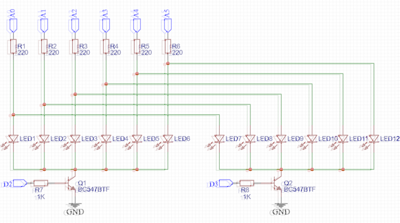
The problem? In two banks of six LEDs each, both LEDs connected to a single Arduino pin would light, even when only one bank was turned on at the ground side. The LED In the bank that was switched on lit brightly, and its corresponding LED in the bank that was off would also be very dimly lit. [mihai] was able to determine that the problem was not due to a leaky transistor, but rather due to a quality of the LEDs themselves.
What is an LED but a diode, and it’s well known that diodes also have capacitance. In fact, this quality is exploited in varactor diodes, a specialty diode whose capacitance can be changed by varying the voltage on the cathode. [mihai] deduced that this capacitance was causing current to flow in the bank that was off. Where was the current going? From the Arduino pin that was on, through its attached LED, and then into the rest of the bank of LEDs, charging them like capacitors. [mihai] hasn’t seen this before, but theorizes that for the latest batch of high efficiency LEDs, this minute current is enough to light the LED through which the current is flowing.
[mihai]’s solution is an elegant hack which he’s made available for your perusal. You might also enjoy this introduction to diode basics by W2AEW. If you have any great diode or LED hacks of your own, be sure to drop us a line!


On this subject, LED’s these days are available in only three levels of brightness; blinding, eyeball-melting, or “starting the back of your head on fire” brightness. I believe that Oscar Vermeulen had a great deal of trouble finding dim, old-timey, “deep red” LED’s for his PiDP-11 replica. Who makes GaAs or GaAsP 670 or 700nm LEDs today?
Agree, this is mental. I rework many boards to replace the ballast resistor with a larger value so that I can see the silkscreen on the board when the LEDs are lit.
Yeah, it’d be nice to have LEDs for status that don’t light up an entire room like the Activity LED on my PC case…
I put a thick piece of paper between the LED and the case to reduce the brightness. I have done that for USB sticks, Hub, PC etc.
The perpetuated 20mA is the max. operating current not the nominal amount! LED these days only need a couple of mA. The new Jade green ones are insane. I can light them up just by stray static and I am using around 10k series resistors in some cases.
I use green 0805 LEDs for power rail status in many of my designs. I choose resistors to give each LED 0.5mA, which is plenty for debugging.
Personally I like these bright LEDs because I can under-drive them and their loading on the rest of the circuit is negligible.
For those “annoyingly bright LEDs in commercial products” I sometimes use a black marker pen (like a “Sharpie”) to cover the LED. Pleny of light still gets through, so you know the LED is on, but it’s much less dazzling.
“Wait for transistors to fully switch off”
The Ft of these devices is 300MHz. There shouldn’t be any need to wait for anything to turn off if you’re cycling them at 1kHz. I wonder what leads to this sort of overthinking.
Actually transistor switch-off time is a thing. It’s explained here https://en.wikipedia.org/wiki/Schottky_transistor#Mechanism
But this time is short enough to make it not matter when using the Arduino digitalWrite function, as it does a lot in the background and that slows things down enough to “include” this delay. However the switch-off time does produce a noticeable effect if you directly write the PORT registers, like this:
// turn off bank
PORTD &= ~(1<<PORTD2);
// turn off all LEDs
PORTC &= 0b11111100;
An easier way to solve this is to drive the low side of the LEDs through a buffer instead of a single transistor. Low = LED bank on, high = LED bank precharged so it doesnt’ ghost.
A pullup resistor would also work.
You’re right, a pull-up to the collector also works, and requires no extra pin or changes in the software.
As a ball park figure of 10mA per LED, the sink current is 60mA. The Hfe of the transistor is 100 – 800. Worst case Hfe 100 you need 0.6mA transistor base drive current. Driving from 5Volts and subtracting Vbe 0.9V total drive source 4.Volts shows that the Base series resistor need be about 6k8. So driving the base through 1k Ohm is clearly saturating the Base Emitter junction.
The first thing to try is to increase the base series resistor. If you still need to go further then place a resistor from Base to Emitter. Use this as a voltage divider aimed ate about 1Volt Vbe and still be able to supply 0.6mA Ibe.
Ahhh then I realized that 6 and not 12 LED current limit resistors (aimed at about 22mA) so extra diodes or extra resistors or place the resistors below the diode rather than above.
Alternately use the GPIO as High or tri-state as an input and never low.
I don’t know very much so thank you for this article.
first, delay(0.050) is equals to delay(0). the delay function parameter is unsigned long.
second, if the problem is really capacitance, why not set A0..A5 to high impedance.
You’re right, for this sketch the tiny delay is just for “academic purposes” :) And you’re also right about setting them to high impedance, Paul McClay also suggested it in the page comments and I confirmed it works perfectly!
While the brief flash upon switching LEDs may be capacitance, I’m skeptical that this is the cause of the constant dim glow for the whole second as seen in the animated gif on the project page.
My first guess would be leakage current through the reverse biased LEDs. The datasheet of the LEDs specify a maximum of 10uA, so up to 50uA for this circuit.
The dim glow was on for the whole second because for that animation I actually had the banks switched at ~1kHz. When slowing everything down the fainting turned into very brief pulses of the affected LED when the other bank was being switched on.
Ah, I missed that you are pulsing the LEDs in the first example. I agree, in that scenario stray capacitance sounds plausible.
It’s certainly a consideration – bright LEDs can be surprisingly sensitive to any leakage current flowing. In this case he’s toggling the LEDs every millisecond (approx) so the “off” LED is seeing a 500Hz square wave at its anode.
Showing the brief flash would have made this clearer – the first animated gif is showing them blurring into each other.
I agree, I think it might be that big tangle of wires acting as an antenna or some such effect. It may be similar to getting leds to light up by touching them when they’re in a circuit. That’s what it looks like, and that’s what it sounds like to me.
It only lights up the first one in that bank because of the diode drop that prevents the others from getting enough power to light. This is my guess.
I too think the capacitance theory doesn’t hold water.
Even at 1KHz that’s 1ms per pulse, but the time constant of 22pF and ~100 ohms is in the order of nanoseconds (doing it in my head).
Also if it were capacitance-related you would get a flash and decay, not a solid constant lighting up as per the video.
My bet is that there’s just some leakage which has been removed by the new circuit, which does the job, so well done for that.
You’re right, it actually is a *very* brief flash, my video wasn’t too inspired as I was showing the 1kHz switching between banks. So all those very brief flashes get integrated by the camera into the constant lighting. When slowing everything down to ~1Hz you can only see the dim flashes.
I see what you did with the illustration; well played.
A simple way that works in most situations is to place a 10kohm resistor in parallel with each LED. While the LED only starts conducting at around 1.5V and simultaneously produces light, the resistor will conduct at lower voltages and quickly charge any parasitic capacitances.
You’re right, a reistor in parallel with each LED also does the job.
This also help you prevent ESD damages for LED mounted in panels.
I didn’t, so i bought new, expessive glasses. Now i’m deep in debt and the bank took my home. Its -10C in here now, but yesterday it was almost -20C, so i guess i’ve got that going for me.
That was a reply to socksbot. Thank you comment system, again.
More likely to be that there’s still some drive to the transistor bases. How are the outputs driving them configured? Do they pull down properly to ground?
Try replacing the transistors with PNP and see what happens.
You’re right, this is also potentially a problem. The outputs are normal Arduino digital pins, in push-pull so they’re slammed to GND pretty hard. But when commanding the pins directly through the PORT registers things are too fast and the LEDs are powered before the transistor has time to fully switch off. That’s why I added a 50us delay after turning the transistors off. However when using the Arduino digitalWrite() function, this is rather slow and doesn’t need extra delay.
“Then line A0 goes high because in the next bank LED7 should be on. At this moment LED1 flashes briefly. Afterwards the bank containing LED7 is turned on by bringing line D3 high.”
Now I’m wondering why LED7 didn’t flash at the same time as LED1. At full speed the flash would be masked by the subsequent switch on, but I’d have expected to see it at slower switching rates.
This took me quite some time to figure out, thanks for a very interesting question! It has to do with what happened the last time LED7 was on.
Last time LED7 was on and being switched off I first turn off both transistors and afterwards I turn off the A0 line. So in between these two events, LED8..LED12 were being charged through LED7. Then on the following cycle (LED1..LED6 addressed, all off) that charge has nowhere to go. Advancing to the next cycle (the one quoted) we find LED2..LED6 discharged and LED8..LED12 charged, leading to the difference.
I tested this by first switching off the LEDs and THEN turning the transistors off, and I got the behaviour you expected — both LED1 and LED7 flashed.
I normally love the artwork but I’m getting older. It took a moment to verify there really was a double effect in the picture and it wasn’t my eyes acting up!
I had the same issue xD
ive had capacitance issues as well,
but usually it is rooted in the input capacitance of a driving transistor.
taking notes from SMPS’s greatly helps,
i find either a resistive voltage divider,
or just a load before the regular resistance usually eliminates the problem.
just remember to thevenize resistor values to determine if it meets your specs.
(you may have-to)
in the dark when im trying to retain my nightvision,
AND using LEDs that happen to be focused at me,
i almost always use resistors at or above:
4k7 to 15k for red and amber,
10k to 100k for warm-white
10k to 220k for orange pure-green, royal-blue, and cool-white.
of course, i need a flashlight to change any components,
ancient flouro-backlit LCD monitors dont like being switched on and off all night…
Would reverse biasing diodes prevent this issue.
An alternate fix that doesn’t require precharge pins or extra hardware is to use high-z states instead of lows.
The voltage across every LED in the OFF bank would be equal since the ‘capacitance’ isn’t grounded.
Just put a pull-up on the collector of each transistor Q1 and Q2, which ensures that the corresponding LED sees no forward current. The downside is that the LED does see reverse voltage, which shouldn’t be a problem for Vcc of 3.3 or 5V, as most LEDs can manage reverse Vcc – Vce – Vled, 3.2V say worst case at low temps, without trouble.