With a 555 on the BOM, you never know what you’re going to get. With 40 of the versatile timer chips in a build, you might just get something completely unexpected, like this 555-based eight-bit digital counter.
This one comes to us by way of [Astronomermike], who chose to make a digital circuit with nothing but 555s and a largish handful of passives as his entry in the current 555 Timer Contest. The ubiquitous timer chip is not exactly the first chip that comes to mind for digital applications, but it does contain an SR latch, which only requires a little persuasion to become a JK flip flop. His initial design for the flip flop that would form the core of the circuit had a pair of 555s surrounded with a bunch of OR gates and inverters — within the rules of the contest but hardly in its spirit. Luckily, the 555 makes a fine inverter too, and along with some diode-resistor OR gates, the basic counter module was born.
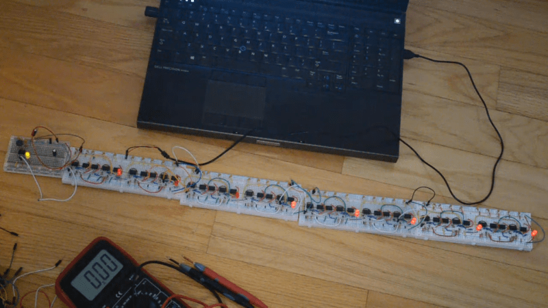
The video below shows the design and build, as well as the trip down the troubleshooting rabbit hole courtesy of a bad breadboard. Each half-nibble stage of the 8-bit counter occupies a full breadboard with ten 555s; the whole 40-chip string actually works and looks pretty cool doing it.
Truth be told, this is exactly the kind of thing we had in mind when dreaming up this year’s 555 contest, so good on [Astronomermike] for thinking outside the box for this one. To see what other uses people have found for the chip that keeps on giving, or to get your entry in before the deadline on January 10, head over to the contest page.


Could have done that with a Raspberry Pi
B^)
Why stop there… I’ll raise you a Raspberry Pi made entirely made of 555s. Then use that to emulate a circuit that makes up a digital counter made up of 555s. Now that we’re at it, let’s get the those IO pins to control another counter made of physical 555s.
Touché :,)
Now make it 7 segment using only 555s!
B^)
well you could, use one 555 to generate a sawtooth like signal, use 10 555’s each one must operate as a comparator and connect it’s output to the required segments of the 7-segment display using diodes.
Some trickery with the resets of the 555 may be required in order to realize the proper windowing comparison functionality of the 555, but it should be doable. And if some extra inverters required (these can be made with 555’s as demonstrated in this video).
The sawtooth signal is basically an analog counter here, but who cares.
Regarding the project of this article, cool. Nice to see it working with multiple stages.
Thanks [Jan]!
I was half flippant / half serious when I posted that!
Thanks again, maybe it will inspire someone to give it a try!
Hmm,
I would have to breadboard it to test … but I think you could get away with using two 555’s per FF
Must investigate ;)
Report back to us, if nothing else, it could be “Fail of the Week”, and the resulting feedback could lead to success.
Quick and very dirty … only runs at 12V and higher. But it works :)
https://www.youtube.com/watch?v=jLwOYWj4JCc
Too bad it can only count to 555…