We don’t see many EMG (electromyography) projects, despite how cool the applications can be. This may be because of technical difficulties with seeing the tiny muscular electrical signals amongst the noise, it could be the difficulty of interpreting any signal you do find. Regardless, [hut] has been striving forwards with a stream of prototypes, culminating in the aptly named ‘Prototype 8’
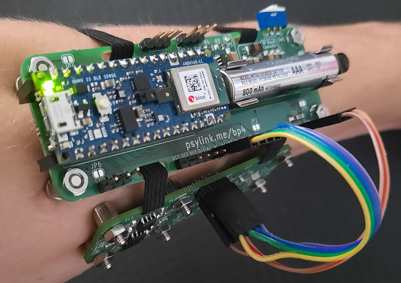
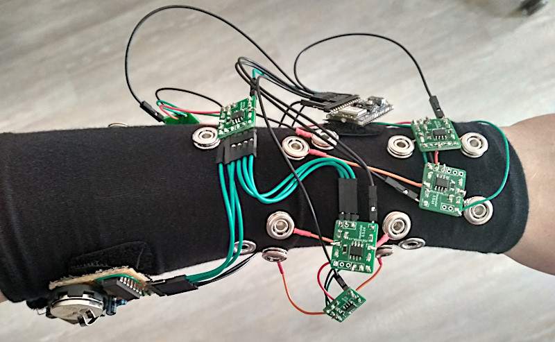
The current prototype uses a main power board hosting an Arduino Nano 33 BLE Sense, as well as a boost converter to pump up the AAA battery to provide 5 volts for the Arduino and a selection of connected EMG amplifier units. The EMG sensor is based around the INA128 instrumentation amplifier, in a pretty straightforward configuration. The EMG samples along with data from the IMU on the Nano 33 BLE Sense, are passed along to a connected PC via Bluetooth, running the PsyLink software stack. This is based on Python, using the BLE-GATT library for BT comms, PynPut handing the PC input devices (to emit keyboard and mouse events) and tensorflow for the machine learning side of things. The idea is to use machine learning from the EMG data to associate with a specific user interface event (such as a keypress) and with a little training, be able to play games on the PC with just hand/arm gestures. IMU data are used to augment this, but in this demo, that’s not totally clear.
All hardware and software can be found on the project codeberg page, which did make us double-take as to why GnuRadio was being used, but thinking about it, it’s really good for signal processing and visualization. What a good idea!
Obviously there are many other use cases for such a EMG controlled input device, but who doesn’t want to play Mario Kart, you know, for science?
Checkout the demo video (embedded below) and you can see for yourself, just be aware that this is streaming from peertube, so the video might be a little choppy depending on your local peers. Finally, if Mastodon is your cup of tea, here’s the link for that. Earlier projects have attempted to dip into EMG before, like this Bioamp board from Upside Down Labs. Also we dug out an earlier tutorial on the subject by our own [Bil Herd.]


Wow, this looks indeed great. But for some of the movements (punch-like forward movement, twisting/rotating the arm) I am sure that they can be detected using a gyro/acceleration sensor more easily. AFAIK the muscles in the forearm are for moving the fingers/hand only. So anything related to the movement of the forearm should be based on other sensors or EMG sensors placed elsewhere (upper arm).
Author of the project here. Thank you :) And sure, you can capture many of the motions with an inertial measurement unit (IMU) as well, and sometimes I’ve been wondering why I’m even bothering to use electrodes, but as you said, the fingers are controlled via the forearm muscles and might not be easily captured with an IMU on the arm.
Another advantage is that EMG can theoretically capture signals before any motion happens, so with a more advanced design, you could control the computer without any actual movement.
And for the record, I’m playing the game in the video without signals from the IMU (as you can see in the signal visualization window next to the game)
The reason why you don’t see more medical hacks is because pretty soon the “safety police” will show up telling you how dangerous your device is, leading to endless back-and-forward debates about the safety of your device. Looks interesting and will study it further, good luck when the “safety police” gets hooked into this.
Project author here. The website says “DO NOT USE ON LIVING ORGANISMS” and other similar warnings, so there’s no risk of harm to any living organism :)
I’ve been dead inside for years now, so I think I’ll be safe
Yes but your lovely carapace may become damaged in some unknown manner and that would make us all very sads. Please be carefuling!
Could be a neat opportunity for bodybuilders to simulate a brain !
More seriously, this is a very awesome progress toward a cheap computer interface for impaired people.
> bodybuilders to simulate a brain
Thought we were already past body shaming directed to anyone, given the current year, but I guess it’s just a handful of people who really are shielded from unnecessary bullying, innit?
Maybe grow thicker skin and learn to appreciate a joke? It’s a harmless joke, and if you take offense, you’re in a very small minority.
I think you only get that pass if the “joke” is funny. Thicken your skin mate, it’s just some online criticism.
Fantastic work! A very nice start to an EMG-based ‘HMI’.
For anyone looking to get into biosignal acquisition and processing, Tranquillo’s “Biomedical Signals and Systems” is an excellent primer for the field
A word to the wise: always work with the mindset of ‘safety first’ when working with equipment that connects to anything living. Make a habit of using optocouplers, reverse current protection, and high input impedance amps whenever designing biosignals equipment. Even a relatively small shock can be very…unpleasant if you’re not careful
Project author here. Thank you for the suggestion :) I have to look into adding safety features to PsyLink at some point… so far, it has none of the ones that you describe, but thanks to a low voltage, relatively small capacitors, and a mere AAA battery as a power supply, there should be a very low risk of electric shocks anyway.
“there should be a very low risk of electric shocks anyway.”
Where’s the fun in that?
B^)
Given this is powered by a single AAA battery, and there are no giant capacitors or nichrome wires deadshorting the power circuit, i think this is only slightly more dangerous than a digital watch.
FYI: Fantm is another open source/hardware EMG project: https://www.getfantm.com/
Can we have a picture of the arm after wearing this for 1h?
I mean, let us know how is the footprint of the device. Those bolts may give a good pattern.
Author of the project here. The spacer screws that I’m using in the screenshots are indeed not exactly good to the arm :). I experimented with different electrodes and e.g. steel dome nuts are pretty comfortable, but the signal I’m getting from them is not quite as good, so at the moment I’m choosing quality over comfort :) There sure are better options out there, and should be easy to integrate onto the existing PCB design.
As the website says “DO NOT USE ON LIVING ORGANISMS” you must mean your cadaver’s arm, of course :-)
How tight does the strap need to be to get the spacers to get a strong enough signal? Is it tight enough to start hurting after a few minutes?
I’m surprised that you get a clean enough supply using a boost converter. One idea might be to use a LiFePO4 cell – they come in AA and AAA sizes, and have a nominal voltage of 3.3v. If that’s enough for this application, then you get a really clean supply. They’re pretty wonderful power supplies – lower power density than LiPo, but with a calendar life of 20 years or more, typically 2000 charge cycles (to LiPo’s 500), and very safe. They’re the cheapest per Wh over useable lifetime of all modern rechargeable batteries.
I’m using a AA-sized cell for a robot that moves slowly. It powers everything directly – no voltage regulator needed.
Hi Adam, thanks for this suggestion. Project author here. I actually looked into this before, and here are the problems:
1. The voltage that comes directly from the battery declines over time as it discharges. This might change the exact values of the signals over time. It would be unfortunate if you train the AI to recognize certain signals, and half an hour later, the signals look differently. This effect may be negligable though, I haven’t experimented with it yet.
2. The instrumentation amplifiers actually need 4.5V at least, but I’m looking into options that require less voltage.
3. I’m unsure about the safety, lithium batteries seem to tolerate short circuits less well than NiMH batteries, and I don’t want a bomb strapped to my arm :D but maybe this doesn’t apply to LiFePO4
Another (tiny) advantage is that one can get cheap 1.2V AAA batteries everywhere in the place I live, while I don’t recall seeing 3.3V AAA batteries in supermarkets.
But apart of that, 3.3V straight from the battery would be much better indeed. The boost converter circuit is indeed theoretically quite noisy, although I haven’t found a noticable effect on the signals that I’m receiving. But still, if I could get rid of it, it would save money, space on the PCB, assembly time, and eliminate points of failure. Once I find good amps that work with 3.3V, I’ll give it a try.
Not sure if it has the specs you need (or even if it’s the right class of amplifier), but the uCurrent uses the MAX4239AUT: https://www.digikey.com/en/products/detail/maxim-integrated/MAX4239AUT-T/2280139
It takes 2.7-5.5V.
If you’re not seeing issues with the boost converter, then I think this is just a bikeshed, haha. You’re right about the voltage dropping over time – it’s a pretty small change for LiFePO4, but that still may be an issue. I didn’t realize that you were using NiMH cells, those are a good choice.
I did an audio design which ran on an 18650 lithium cell, but needed 9V, so I used a boost converter at 10V, then a linear regulator to drop it down to 9V. That worked pretty well, but it does waste some power.
LiFePO4 are pretty safe, but NiMH are safer.
This is a cool project – thanks for sharing!
I made a 12 lead ECG a while back with SMPS as an isolated power supply, power supply noise is easier to deal with then you expect.
Hmm. Add and IMU, train the network to recognize finger positions, and this can make a hell of a next-generation VR glove. Good luck with your project.
Hey :-) A really cool project, and excellent documentation! Kudos!
Hmm, looking at your schematics – out of curiosity, why did you decide to use an op-amp circuit instead of a precision reference for the reference voltage generator section? While certainly more expensive, the precision ref. solution would have significantly higher temperature stability and much lower drift (I’m thinking something like lm385 or REF05 series). Or is such a high precision less of a concern in this case?
Project author here. Well, to be honest, this is the first time I hear about precision references – I have software developer background, and I’m still learning electronics. The reference voltage is one of the critical parts of the system and I am thankful for your suggestion! :) Will put it on the list of things to try out.
Fantastic! Can you use it to control a robotic hand or a DIY robotic arm? It could be helpful for debilited people!
Currently you can just press keyboard keys with it, and theoretically you could control a robotic arm/hand (or pretty much anything) by pressing keys, so yes :) But it hasn’t been tried out yet.
Hi, is there a version of this that may work for forearm muscles? I want to determine the force exerted by measuring EMG signals when someone closes their hands.
Sorry, I see it is for a forearm. Can it determine this force rather accurately?