[Gregory] is building some microwave gear and wanted to convert a 3.3 GHz signal to a 12 MHz intermediate frequency. You might think of using a mixer, but you’d need a local oscillator of nearly 3.3 GHz which is not only hard to build, but also will be very close to the signal of interest which is not a great idea. Instead, [Gregory] opted for a sampler, which uses an effect you usually try to avoid — aliasing — to allow downconversion with a much smaller local oscillator. You can see the design in the video below.
In the case of converting 3.3 GHz to 12 MHz, the local oscillator is around 100 MHz. How does that work? Watch the video and find out. The final project will triple the 3.3 GHz signal and we presume the 12 MHz downconvert is to easily phase lock the frequency using a PLL (phase-locked loop).
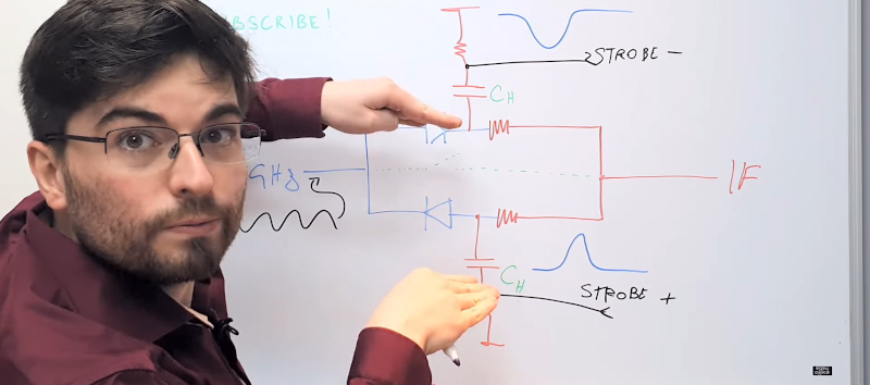
The circuit is little more than an electronic switch and a capacitor. The first part of the video covers the theory of operation. About 7 minutes in, the whiteboard talk gets more practical, using diodes as switching elements. At the very end, we see he has a PC board design but it isn’t generally available. Still, the theory explanation is well worth the 20 minute watch.
If you want some ideas about prototyping microwave gear, there are some tools available. If you want to dig more into PLLs, there’s a lot of info about that in previous posts, too.


Nice job teaching the fundamentals of a sampling system. I honestly didn’t know how he was going to get the precisely-matched positive and negative pulses. I knew there would probably be a transformer involved, but the way a stepped recovery diode works in this circuit was new to me.
The whole topic plus your anecdote describes what I find so fascinating about electronics. Even though we’ve (collective humanity we) built all these parts, we’re still theorizing and experimenting with how they operate in certain situations and combinations. The joule thief is another good example of that. It’s still a bit mad scientisty at times, and I love it.
It’s probably easier to explain with graphical plots of the math.
We used to use a system like this with 10 storage capacitors and 10 hold gates to do block down conversion is such a way that we could get very strong (filtering slopes) rejection of adjacent frequencies.
It was our analogue equivalent of the “brick wall” filtering you get with single bit oversampling.
It was used a lot in wide band telecommunication like microwave links that had a very large number of “voice” channels resulting in a very wide bandwidth.
Oddly this technique is still better at microwave frequencies as even modern DSP slices just can’t go there. (They actually “can” go there but they need some analogue help)
The term we used for this technique when there were multiple (10) sample hold points is a “bucket brigade”.
The famous “Switched capacitor audio filter” or SCAF chip of the 1980s. Most popular was the MF10 and even radio shack sold the MF10 chip at one time in the 80s. Couple dollars at most.
You could buy $20 of old telco inductors and add a bunch of capacitors and have a “meh” audio filter for ham radio the size of a lunchbox or use the MF10 and it worked better and was a tiny solution to the problem.
Intel has some FPGAs with Direct RF capability. A staggering 64Gsps. well into and past microwave capability and into millimeterwave capability. https://www.intel.com/content/dam/www/public/us/en/documents/solution-briefs/a1152797-sb-fpga-with-integrated-data-converter-technology.pdf and the Xilinx RFSoC pretty much covers half of all the microwave bands as well
Yes but there’s a number of points about that chip –
1) It doesn’t look like it has any HDL encodable DSP, instead it has fixed logic DDC and DUC (ASIC)
2) It doesn’t do any band splitting or combining, what it calls a “baseband” is the whole band to TX RX
3) The FPGA is for phase array synthesis only (well almost “only”)
4) Knowing Xilinx I didn’t bother go looking for a price, nothing short of a state govt/govt department could afford this chip.
There are some differences to what I was explaining.
Firstly, I was explaining something used for microwave links so definitely not anywhere near audio and above what most are familiar working with in the RF range.
The second point is that with RF your generally trying to pick one CW/audio/data or small baseband out of a sea of RF signals.
With a microwave link you have to decode *everything* back to it’s original small band – usually one voice channel.
So with test equipment where you didn’t need to see the content of the channel you could use the technique described in this article. So for an example, you could look at a channel using QAM (using this technique), send it to a CRO (Scope) and see the eye pattern to know that it is within constraints (all is good). You couldn’t decode the data because the data rate and frequency are different to what the scope is getting. It’s just getting time division samples that don’t match the data rate or original data.
Now, on the other hand, if you have to decode ALL the sub-bands then you have a filtering nightmare as there is no buffer regions in the spectrum for filter slopes.
That is when the 8/10/12/16 time division samples (into the same number of capacitors) was used so you could split the whole microwave signal (with some pre-down conversion) into 8/10/12/16 smaller bands where more conventional technology could be used to split it up into smaller groups and eventually into single channels (9636 of which).
This was back in the late 70’s – early 80’s. I not sure we even had UHF TV then so it was quite a feat to get microwave communication transmission to work with the technology we had.
For the curios – this is how things were put together. One channel was 700Hz to 3.8kHz
One Group (Three channels) had the original unchanged except for being bandpass filtered as they all were. Added two that were another two channels, one as an upper side band, one as a lower side band and all without a carrier.
Three of these groups went through much the same process to make a mater group. 16 master groups made a carrier (meaning cable, RF, Microwave) baseband and 8/10/12/16 of these made a link.
So the only modulation below carrier only had upper side bands USB, lower side bands LSB and no carrier.
The only carrier was transmitted on a single audio channel as a mix of 1.4kHz and 2.4kHz. so say your local oscillator (many megahertz) drifted so that the 1.4kHz became 1.5kHz, that would mean that the 2.4kHz would become 2.5kHz so the difference between the two was still 1kHz. At the other end one was modulated with the other and the lower side band taken – the LSB of course would be 1kHz and that was the reference (carrier) for the local oscillator at the other end.
This might sound like a lot of stuffing around, and it was, but it was to squeeze every little bit of bandwidthe we could out of the links we had. To do that we needed alternate ways to just filtering channels off because with the tech at the time you couldn’t do better than 12 dB/octave without serious phase distortion.
The solution was to split and then filter because if you tried to split BY filtering then you loose half your adjacent channels.
I believe this is the same technique that the open laser range finder (OSLRF01) used. https://forum.arduino.cc/t/open-source-tof-laser-rangefinder/208188/40 It was a genius design. Unfortunately that dev went commercial with it and took down all the schematics and other info. :/
yeah aliasing is used all the time in order to remove a mixer stage. See it all the time in telecom equipment. All you have to do is put a bandpass filter on the input of the ADC and you can filter out everything but the specific alias band you want. that way you don’t have any overlapping. Be careful tho, you have to account for the parasitics induced by the ADC itself. You can’t just pump 30ghz into a 10msps ADC and expect to see anything, the 3db point is typically not too far past the maximum sample rate of the adc. You can also get around having to have a high frequency local oscillator but stepping down the frequency in multiple stages rather than all in one go.
1. WARNING(?): The YouTube video notes say: “06:52 – Circuit diagram”. False! To actually see the full schematic it seems to me you must go to the Patreon page here:
https://patreon.com/allelectronics
and PAY MONEY for a channel subscription. Am I wrong?
2. This type of SRD driven sampling down converter has been around for decades (at-least). The first published paper on the SRD alone is dated 1960.[1]
Awhile back I found a 1999 US Patent that shows an almost identical circuit used as a sampling phase detector, which may be a better fit for [Gregory]’s PLL disciplined source project than the sampling converter. Take a look at this:
SAMPLING PHASE DETECTOR, US Patent Number: 5,900,747, Date of Patent: May 4, 1999.
a) https://patents.google.com/patent/US5900747
b) https://patentimages.storage.googleapis.com/00/a9/d9/ce4bdc7595802c/US5900747.pdf
This looks quite like [Gregory]’s sampling converter yet it produces a DC output fd depending on the phase difference between the input signal fr in the suggested 2-20GHz range and a reference input signal fo. The patent does not specify the reference signal’s frequency range but it seems to me that provided the input signal is steady-state in time greater than the reference signal’s period, the sampling nature of the phase detector should work with a reference signal that is significantly lower in frequency compared to the input signal.
* References:
1. Step Recovery Diode – References
https://en.wikipedia.org/wiki/Step_recovery_diode#References
Boff, A. F.; Moll, J.; Shen, R. (February 1960), “A new high speed effect in solid state diodes”, 1960 IEEE International Solid-State Circuits Conference. Digest of Technical Papers., IRE International Solid-State Circuits Conference, III, New York: IEEE Press, pp. 50–51, doi:10.1109/ISSCC.1960.1157249. The first paper dealing with SRDs: interesting but “restricted access”.
“This looks quite like [Gregory]’s sampling converter yet it produces a DC output fd depending on the phase difference between the input signal fr in the suggested 2-20GHz range and a reference input signal fo.”
This is the standard behavior of any sampler that’s DC coupled, which includes the circuit described in the article. If the input signal is an exact multiple of the sampling signal, the alias signal’s frequency is zero – the input is sampled at the same point on its waveform every time. Sample & hold circuits are often used in phase locked loops as the phase detector for this reason.
As for the Patreon paywall, yeah, this is a disturbing trend on YouTube. It’s bait-and-switch, as I see it.
It’s the inevitable result of YT’s constant incremental tightening of the screws around monetisation. High quality content like this takes significant time and money to create, so it’s disingenuous to complain that you should get everything for free and they should get nothing. You’re still getting a lot even if you decide not to help support him.
But everybody loses. The good thing about the advertising model, is that everybody pays a very small amount, and the producers get paid more than they would by being paid directly by the viewers. It’s NOT just about monetization, but about The Great and Infinitely Fickle Algorithm. YouTube has created an environment of instability for their content producers, and the Patreon solution is a poor workaround at best. You just don’t HEAR from the creators for whom Patreon either wasn’t an option, or just didn’t help enough to keep them afloat. Because those are the creators who are gone.
What do you think would happen to Wikipedia if it became a subscription service? What if we didn’t have free email options? The free exchange of ideas requires both free speech AND free beer.
But here’s the part that’s immediately disturbing, every time: back when we had televison, the serious content was decoupled from the advertising. You had your news shows and your documentaries, and they had their ads, but the presenters never talked about the ads. On YouTube, sometimes 25% of the content is the presenter talking about a product, whether that product is what the creator wants to sell you directly, or is something he’s just pitching for someone else. This is not the right direction.
I don’t have a YT account and I have no clue about how they run the show there.
I like to see interesting and innovative “hacks” that have real life meaning so if there isn’t a schematic available or there isn’t enough information available for the concept to be understood or even perhaps reproducible then a TY clip is disinteresting to me.
Otherwise I couldn’t care less if the clip is done in a professional studio with professional lighting and editing and camera movements. Just a tripod is fine and perhaps don’t get the light behind the subject to often so you don’t saturate the light balance. Also use a tripod because people don’t like being grabbed by their head and slung around the room (as it feels when you start walking around with a camera.
A full setup with light defusers, gimbaled camera, some camera linear rails is all a waste of time if the topic is something I have seen many times before.
On the other hand, interesting content can be done with nothing more than a tripod and mic.
The HP 8405A RF Vector Voltmeter used sampling, it is described here: https://www.hpl.hp.com/hpjournal/pdfs/IssuePDFs/1966-05.pdf
Nice to see that there’s still interest in microwave sampling.
https://patents.google.com/patent/US5162723A/en?oq=sampling+signal+analyzer+5%2c162%2c723