If you read old antenna books, you’ll probably see the idea of phased vertical antennas. These use certain lengths of coax to control the phase of a signal going to three verticals in a triangular configuration. Depending on the phasing, you can cause the array of antennas to be directional in one of three directions. [DX Commander] designed a very modern version of this antenna and shows the theory behind it in a recent video that you can see below.
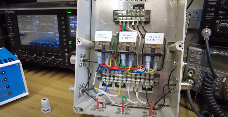
It seems another ham built the antenna and a control box for it which he’s sent to [DX Commander] although he hasn’t set it up yet to create an 80 meter directional antenna. We’ll be interested in seeing how it works in practice.
Of course, the phasing delay line and the verticals will be tuned to a specific frequency, so you can’t expect this to be a broadband system. It isn’t small either since the verticals are placed a quarter wavelength apart and you need about the same amount of coax for the phasing cable (accounting for velocity factor).
The control box can select which vertical gets the delay and that controls the direction. You can also switch the delay out completely and wind up with an omnidirectional antenna.
This is probably not going to wind up being a cheap antenna, especially on 80 meters. While you don’t often see phased arrays at HF, they are more common at higher frequencies.


ON4UN wrote about phased verticals in his classic book, Low Band DXing, so this isn’t new territory. Not cheap, but no gain antenna for 80 meters is due to the size of the elements. Phased verticals aren’t quite as difficult to build for that band as a Yagi, even a shortened one, and may be more acceptable to the neighbors.
if it is set up properly with a good ground field (in other words, lots of radials), this should be an effective antenna. I’m looking forward to seeing the real world results.
Actually the majority HF/MF phased arrays are AM stations, which are slightly lower frequency than 160 meters. These things are very sensitive to other vertical conductors within a mile or less detuning the pattern. This and the need to build multiple vertical radiators (towers) for 80 or 40 meters ( typically 5/8 wavelength) and the need to create ground radials on all towers make this difficult to do in your backyard unless you have huge real estate and plenty of $$. Keep in mind that antennas don’t have any actual power gain, only directionality that takes power from some directions and adds it into other directions. Phased arrays can be very, very effective when done right.
“[..] Keep in mind that antennas don’t have any actual power gain, only directionality that takes power from some directions and adds it into other directions. Phased arrays can be very, very effective when done right.”
True, except maybe, microwave antennas.
Parabolic dishes do increase the surface, opposed to using the antenna in the middle alone with the reflector.
They are a bit like magnifiers, especially to receiving antennas (think of sat dishes).
Likewise, an array of Yagi antennas, side by side, can essentially do the same.
But then, you’re using multiple antennas, essentially, so your statement stays true. :) vy73/55, Joshua
*alone without the reflector
Sorry for the typo (caused by my smartphone).
There was a very popular CB antenna called the Super Scanner that had three vertical dipoles and a control box. It allowed the user to designate one of the three vertical dipoles as the driven element, and the other two vertical dipoles would be modified (electrically) to act as reflectors.
That was almost 50 years ago.
http://home.ptd.net/~n3cvj/superscanner.htm
Cool! Thanks for sharing! 😎👍
The other articles on that site are a fascinating read, too. Even for hams, imho.
Vy73/55, Joshua
Ken, I owned one of those back then as a teenage cb-er. Tower mounted it was a very effective antenna. Sadly I never got to transmit with more than 4 watts but it was good on receive and the switch phasing had decent rejection and good gain.
50 odd years ago I wrote a few thousand lines of DG Nova assembly language code to control a large automated phased antenna array direction finding and tracking system (you can imagine the kind of customer). The three verticals were each about 100 meters tall. The system required a container full of equipment including a Rolm 1602 (ruggedized Nova 1200) with a hard disk, a prehistoric software defined radio, and a then super expensive 12 inch 1024×1024 pixel plasma graphics display to show the emitters and signal strengths. It worked pretty much as described, except the length of the delay for each antenna was completely under software control. With some fancy statistical processing the system was able to determine bearings to multiple emitters simultaneously to within a degree or so (or, at least, that’s what the customer told me).
I did all of the development work using a Nova 1200 simulator and cross-assembler/linker running on a PDP-10. Everything worked the first time on the real hardware, except I got the Y coordinate origin backwards so the display was upside down. Oddly enough, reconstructed versions of this simulator and assembler/linker still exist as part of the SimH package.
A three element phased array is quite commonplace in ham radio and isn’t that big a deal. Four element arrays are common, and there is an 8-element phased array for 160m at NA7TB in southern Arizona.
It seems to me the exiter could be split into different signals each with a simple variable phase shifter to seperate Power Amplifiers and and antennas…