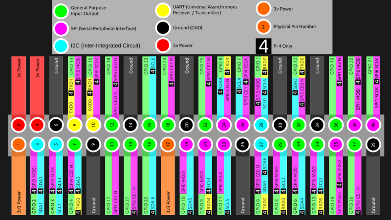
We’ve gotten used to the GPIO-available functions of Raspberry Pi computers remaining largely the same over the years, which is why it might have flown a little bit under the radar: the Raspberry Pi 4 has six SPI controllers, six I2C controllers, and six UARTs – all on its 40-pin header. You can’t make use of all of these at once, but with up to four different connections wired to a single pin you can carve out a pretty powerful combination of peripherals for your next robotics, automation or cat herding project.
The datasheet for these peripherals is pleasant to go through, with all the register maps nicely laid out – even if you don’t plan to work with the register mappings yourself, the maintainers of your preferred hardware enablement libraries will have an easier time! And, of course, these peripherals are present on the Compute Module 4, too. It might feel like such a deluge of interfaces is excessive, however, it lets you achieve some pretty cool stuff that wouldn’t be possible otherwise.
Having multiple I2C interfaces helps deal with various I2C-specific problems, such as address conflicts, throughput issues, and mixing devices that support different maximum speeds, which means you no longer need fancy mux chips to run five low-resolution Melexis thermal camera sensors at once. (Oh, and the I2C clock stretching bug has been fixed!) SPI interfaces are used for devices with high bandwidth, and with a few separate SPI ports, you could run multiple relatively high-resolution displays at once, No-Nixie Nixie clock style.
As for UARTs, the Raspberry Pi’s one-and-a-half UART interface has long been an issue in robotics and home automation applications. With a slew of devices like radio receivers/transmitters, LIDARs and resilient RS485 multi-drop interfaces available in UART form, it’s nice that you no longer have to sacrifice Bluetooth or a debug console to get some fancy sensors wired up to your robot’s brain. You can enable up to six UARTs.
How To Use These Interfaces?
Enabling these interfaces seems to be straightforward, and people on Raspberry Pi forums and other places have been test-driving them for their own endeavors. All three kinds of interfaces can be enabled using dtoverlay lines in config.txt. For SPI, the [MaSt] blog helpfully provides some examples:
# enabling SPI6 with two CS pins - one on GPIO16 and other on GPIO26

dtoverlay=spi6-2cs,cs0_pin=16,cs1_pin=26
For I2C and UART, Raspberry Pi forum threads provided a few examples. I2C example:
# Enabling I2C3, with SDA on GPIO4 and SCL on GPIO5

dtoverlay=i2c3,pins_4_5
# Enabling UART, with RTS and CTS pins (omit the 'ctsrts' part to disable them)

dtoverlay=uart3,ctsrts
From here, these interfaces will appear as you’d expect them, as /dev/spi6, /dev/i2c-3 and /dev/ttyAMA* respectively. (The serial ports don’t have aliases yet, so you’ll get one more /dev/ttyAMA port added to existing ones.)
We were surprised to learn about these new peripherals, and maybe you were too? We can’t wait to see what you’ll do with them.
Main image remixed from Raspberry Pi 4 GPIO pinout diagram by [Les Pounder].


Meh. Needs a true LPT port still.
Just think of the possibilities for controlling old CNC machines.
Seriously?! All you need is a serial adapter on single I2C or SPI port. If your hold up is an LPT port then you’re already out of your depth.
You could probably even do that in software plus a bunch of level shifters.
Unless the OP was being sarcastic, then this.
You don’t even really need a serial adapter, though that would work well. There are a good few examples out there of people using the GPIO as straight parallel output, and form a quick google their CNC would likely need 9-12 outputs and 0-5 inputs, which the PI is more than capable of. I’m not super familiar with the GPIO layout, but odds are you could get all the outputs with one register bitmask and the same for the inputs. A quick google shows a good few examples of people interfacing with similar parallel interfaces with RPi GPIOs. It should be able to run reliably at 100kHz with a nice C/C++ driver, of which I saw a few good examples.
Even under Linux you can get speeds that is needed to replace a Motorola 68000 in a Amiga. Pistorm is the project name.
Depends what you need the LPT port for. If you’re interfacing to a simple printer, sure. Some years ago, the company I used to work for had to retire some legacy equipment that wouldn’t work with LPT ports over USB, because the associated software required a bidirectional LPT port mapped in the processor’s I/O space.
That software would never run natively (if ever) on the Raspberry Pi’s ARM CPU anyway.
That said: There are literally tons of working PCs out there with regular parallel ports, from old retired office desktops to modern, new stock in industrial form factors.
I feel like getting an Intel 8255 PPI clone and hooking it up to some of the GPIOs (8 data in/out and 5 or so control pins) would be a good way to go about adding an the most compatible LPT to a modern platform. For unidirectional parallel port you can build them with a few easy to obtain serial-to-parallel shift register ICs. 3V to 5V can be dealt with more easily if you have use CMOS chips, such as 3V on the SPI input but 5V supply for the outputs. Voltage gets more complicated when you need bidirectional I/O. (but boils down to transistors and resistors which numerous example circuits available online)
No – it’s better to use an I2C I/O expander. A MCP23016 will provide 16 bits of GPIO and there are plenty of examples (and boards) to pick from. Google will come up with a broader range of devices with higher GPIO counts and more features.
The 8255 is a vintage chip – and should be left in the vintage parts bin
MCP23016 is incredibly slow can’t operate above 400 khz. Also not 5 volt tolerant (I checked the datasheet to make sure). So it would not meet any of OPs requirements.
There probably is a I2C connected device that would work but I can’t think of it at this moment.
I’ve bought relatively new 8255 compatible chips for projects in the last 5-6 years. the advantage is porting TI calculator bit banging and other weird dongle protocols was easier. than if I were to use a typical GPIO expander.
A lot of the “parallel” ports on old CNC machines (mills in my experience) were DB 25 serial ports (with low baud rates), not parallel. Spent way too much time finding noise sourcs (they were shielded cables) and other PITA things before going to a serial over ethernet server (“dripper” – it could match the baud rate) solution.
One of the most remarkable advances of 21st century single board computers and you want to shackle it to an 80s era lpt port. I think I’m going to be sick.
You know if that four core ARM processor is too much for you, I am sure someone could dig up an old 8088 that would be more your speed. How about an MFM or RLL ISA card for that whopping one megabyte hard drive you’re sporting?
Jokes aside, why not just get an lpt to usb adapter? With six usb ports, this would probably be the easier solution to trying to choke up one of those high speed data buses with an AMC Gremlin era LPT port instead of tying up a GPIO port?
Why not just use a MESA card? You can get an RPi carrier board (http://store.mesanet.com/index.php?route=product/product&product_id=338) that’ll expand out to a metric ton of IO in any type you want, and off load the real-time sensitive work to the card’s FPGA (and it’ll “just work” with LinuxCNC). If you’re not looking to just “git-er-done”, then you’re probably skilled enough to write a high speed IO driver in C to just write to the parallel IO register, and tune the timing with your own build of Linux with preempt_RT compiled in on a dedicated core…
Yes, I stumbled across this a few months ago while re-reading specifications and was annoyed I didn’t find it sooner. The 1-and-a-half UART comment really strikes home. I fought with that shortage trying to program a PLC with my Pi 3A. I’ve moved on to other things, but maybe I’ll revisit that with my Pi4, now that it’s easier.
Although not directly related to the Rpi4… The Compute Module 4 (CM4) availability is incredibly bad, like I guess most other manufacturers. However, availability was even poor prior to the component shortages from last year. As for when one can get a CM4…maybe, maybe, stock will be available in late August and even so one can only buy one at a time. It is really too bad that this is the case, as the CM4 is quite a nice module with lots of capabilities a a great price point.
The chip shortage bit aside, i thing the foundation under estimated people going after the CMs, maybe they thought it was going to be mostly industrial uses and OEMs.
With the ease we have today to have custom boards made and sent directly to us ready to go, more and more serious hackers will probably start going after the CMs then the regular Pis. The ability to tap into it’s PCIe ports alone open a huge number of possibilities.
Sure, there are other ways to do this today, but I think the foundations commitment to support is something that keep people going back to the Pi more than more capable competing offerings.
The ability to have a tidy package with an RPi and an M.2 NVME is extremely tempting.
This has been killing me.
I finally found a whole 2 of the switch chips (KSZ9567S) that I have been looking for only to find out that there are almost NO compute modules available anywhere…
I was getting close to just saying ‘screw it’ and see if I could try with an nvidia Jetson, but even those are basically unobtainium now too…
Yeah, I feel your pain. I was able to pick up a $25 CM4 a couple months ago, but the other more expensive modules are never in stock. Adafruit hasn’t seen a regular RPI4 in some time also.
I have seen some CM4’s offered on Aliexpress… but at 3-4x the cost. Now, whether the sellers truly have stock on hand is anyone’s guess.
It is truly a shame, as the CM4 looks to be a great product… but if you cannot get any or any in a reasonable time then it is not so great. There are alternatives, but these are far more expensive…
The chip shortage is the new “toilet paper shortage”.
I know a couple folks who bought up more than a years supply of chips for their company “because there’s going to be a shortage”. No kidding, and they caused it.
Laugh’s on them, they’re going to be stuck using ancient parts until 2027 and the competition will have new stuff eventually just like the toilet paper hoarding problem turned out. I bet there’s still hoarders wiping with TP they bought years ago.
Seriously I know guys who dropped the price of a new car or more on hoarding atmega328s and they got tens of thousands of those ancients enough to run their companies for years when the shortages started. Same with every other chip out there, people either got infinite hoard and don’t want to talk because they know they’ll get ripped on, or they got none, none at all.
Anyone know a good way to get multiple SPI interfaces clocking in “parallel” on the Pis? DMA? Trying to mux data across several spi-based interfaces at once with minimal latency / OS impact on throughput.
Are you talking about something like using the Pi as an SPI repeater?
More likely take network traffic eg upd packets from WiFi or ethernet and spit out to SPI.
*UDP
I would like the Pi to have a SPI slave mode though.
And not a single analog port…
+1 Still waiting for one to come
Battery monitoring would be so much more simple with an analog port…
Yes
I have found the UART situation in the RPi4 to be pretty bad. The default UART ports have rather a fixed rate or are connected to Bluetooth. Only one or two of the alternative UART does not intefier with any other default pins like i2c.
After that the (on Python at least) the reliability and max throughput is pretty low. I get regular dropped bytes and the limit of bytes/s is reached quite fast. Much faster than a basic ESP32.
All that was pretty surprising to me as it is such a loved and documented device. It was hart to even figure out hot to enable the lins correctly and it is different for RPi3 and RPi3
It is nice to have more I2C ports. Or it could be if only the I2C driver in Linux allows them to be used. For some weird reason Linux I2C smbus driver allows only the first 256 bytes of a I2C EEPROM to be used.
I tried to connect my max30102, MLX90614 and grove GSR sensor through ADS1115 in separate i2c buses in raspberry pi 4.
I successfully created 2 extra i2c buses by following this instructables tutorial [url]https://www.instructables.com/Raspberry-PI-Multiple-I2c-Devices/[/url]
“# Uncomment some or all of these to enable the optional hardware interfaces
dtparam=i2c_arm=on
dtoverlay=i2c-gpio,bus=3,i2c_gpio_delay_us=1,i2c_gpio_sda=17,i2c_gpio_scl=27
dtoverlay=i2c-gpio,bus=4,i2c_gpio_delay_us=1,i2c_gpio_sda=23,i2c_gpio_scl=24
#dtparam=i2s=on
#dtparam=spi=on”
and i successfully addressed the each devices in each bus.
[img]https://lensdump.com/i/BJFCc2[/img]
[img]https://lensdump.com/i/BJFQZv[/img]
[img]https://lensdump.com/i/BJFVsC[/img]
[img]https://lensdump.com/i/BJF9u5[/img]
[img]https://lensdump.com/i/BJFqAz[/img]
But the problem is i can’t get readings from the newly created buses and gives me error like
Traceback (most recent call last):
File “/home/raspberrypi/Documents/max30102/main.py”, line 18, in
ads = ADS.ADS1115(i2c_4)
File “/usr/local/lib/python3.9/dist-packages/adafruit_ads1x15/ads1x15.py”, line 83, in __init__
self.i2c_device = I2CDevice(i2c, address)
File “/usr/local/lib/python3.9/dist-packages/adafruit_bus_device/i2c_device.py”, line 62, in __init__
self.__probe_for_device()
File “/usr/local/lib/python3.9/dist-packages/adafruit_bus_device/i2c_device.py”, line 172, in __probe_for_device
while not self.i2c.try_lock():
AttributeError: ‘SMBus’ object has no attribute ‘try_lock’
when i execute my program which have attached here.
import time
import board
import busio
import adafruit_ads1x15.ads1115 as ADS
from adafruit_ads1x15.analog_in import AnalogIn
from heartrate_monitor import HeartRateMonitor
import smbus2
from mlx90614 import MLX90614

# Initialize the I2C buses for the three sensors
i2c_1 = smbus2.SMBus(1)
i2c_3 = smbus2.SMBus(3)
i2c_4 = smbus2.SMBus(4)

# Create objects for the three sensors
hrm = HeartRateMonitor(i2c_1)
sensor = MLX90614(i2c_3)
ads = ADS.ADS1115(i2c_4)
channel = AnalogIn(ads, ADS.P0)

# Start the sensor readings
hrm.start_sensor()
sensor.start_sensor()

# Start a loop to read and print the sensor data
while True:
    # Read the heart rate from the MAX30102
    heart_rate = hrm.read_heart_rate()

    # Read the ambient and object temperatures from the MLX90614
    ambient_temperature = sensor.read_ambient_temperature()
    object_temperature = sensor.read_object_temperature()

    # Read the GSR value from the ADS1115
    gsr_value = channel.value

    # Print the sensor data
    print("Heart Rate:", heart_rate, "bpm")
    print("Ambient Temperature:", ambient_temperature, "°C")
    print("Object Temperature:", object_temperature, "°C")
    print("GSR Value:", gsr_value)

    # Wait for 1 second before reading the sensors again
    time.sleep(1)

# Stop the sensor readings when the user presses `Ctrl`+`C`
try:
    while True:
        pass
except KeyboardInterrupt:
    # Stop the MAX30102 sensor
    hrm.stop_sensor()

    # Stop the MLX90614 sensor
    sensor.stop_sensor()