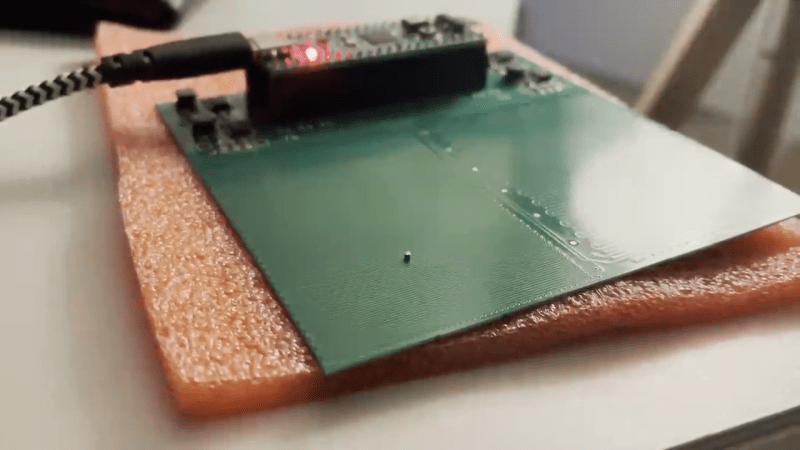
[Kevin Lynagh] is interested in tiny PCB stepper motors, and after reviewing the various projects and patents to-date, decided to give it a try himself. These are basically a stepper motor that’s been unrolled and made flat — traces on the PCB act as the coils and tiny magnetic “robots” act as the rotor.
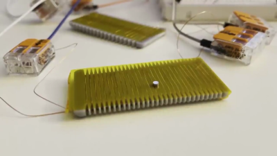
If you want to try this concept yourself, [Kevin]’s post contains an excellent survey of prior art and projects, as well as exploring the theory behind how these things work. He has taken a deep dive in to the theory, deep enough to grasp what’s going on and to build some preliminary prototypes with a bit of confidence. First off was just a hand-wound flat coil as a proof-of-concept. Next was a PCB version that worked almost exactly as planned, although he confesses to burning out a motor driver circuit before stepping back and making some calculations.
We covered one such project back in 2014 and wrote about a Hackaday.io magnetic robot project from reader [bobricius] in 2018. Have you ever used this technology for anything besides a demonstration? Let us know in the comments below.
Thanks to [Adrian] for sending us the tip.


Excellent work/post by [Kevin Lynagh]!
> We covered one such project back in 2014
Two, actually. And maybe more – see Kevin Lynagh’s long list of references. Or search this site. Your site.
Off-topic: time flies!
There is also this https://youtu.be/xPUEOhMBpUw (German language)
The giant model railway in Hamburg is building a Monaco section with race cars for something like 6 years. They had lots of problems getting the PCBs manufactured.
… and directly after posting I see that he mentioned it as well.
For anyone with a day spare in Hamburg, its well worth the time that it takes to walk around too !!
Kevin is amazing. Built his own cell phone years ago. Met him at a conference and he’s as kind as he is clever.
I am genuinely curious about how the rotation of these cuties has been done…?
Imagine this being combined XY plate for 3D printer. Certainly easier than having separate axes for X and Y. There would be lots of interresting challenges tho…
Interestingly as well, anyone involved in semiconductor test will probably have seen something similar to this on a much larger scale. Electroglas wafer probers like the 6″ EG2001 series or the 4080/4085/4090 (which are still sold refurbished at about $90k a pop for 8″ wafers) use a similar linear stepper albeit not built from a PCB. Using laser alignment and correction factors, they could easily achieve micron resolution. My understanding is that they got so good at building them later on that they barely had to apply correction factors to get specifications close to the end of their manufacturing. The X-Y gantry that holds Z-axis lead screw and theta (rotation) correction all ride on an air bearing, so there was nearly zero wear and tear. There are still a lot of companies using these systems from the 90’s, the biggest maintenance headache is the Z-axis mechanicals and the electronics since theyre the things that go bad and are harder and harder to replace.
Sad that Electroglas went out of business – My understanding was that another company bought out the rights and started going after people who were repairing them, though recently there are more people available to service them.
And yes, I thought about taking a decommissioned system home a time or two to make a 3d printer. Just never could justify the space as it’s a full 30″ deep 48″ wide instrument that needs pallet shipping…
I think I’ve seen similar 2D handling “robots” by Siemens or Bosch, but these are 2D (planar) stepper motors, i.e. the “translators” are active and thus need wiring, while the plate is the passive stator.
Can’t find it, but check out these levitating platforms:
https://www.bosch.com/research/know-how/success-stories/planar-robots/
https://www.youtube.com/watch?v=RYETmzAbnpo
This kind is what I meant:
https://www.youtube.com/watch?v=cw_F3CwUM7Q
But nowadays levitating mover platforms are all the rage:
Beckhoff:
https://www.youtube.com/watch?v=7kC-G1kljbA
Philips:
https://www.youtube.com/watch?v=CEK7bfBLTCk
B&R Acopos 6D
Are they not still in business? Their website has a copyright date of 2022.
http://www.electroglas.com
I thought to remember something similar more recently then 2014
https://hackaday.com/2019/05/09/the-two-dimensional-stepper-motor/
In the ’90’s , a company called Megamation in Princeton, N.J. made a version of this technology wherein the Sawyer motor was overhead and the robots were suspended by magnets. The first use I know of was to probe PCB’s at AT&T. I bought a four-headed version in an attempt to assemble some multichip opto products by using pattern recognition to make fine correction to positioning. The capabilities of optics, cameras and AI weren’t anywhere near where they today, and I put my career on the line in the attempt. It was fun to try, and if I were thirty years younger, I would probably try it again.
if we can control more robots, independently, they connected by a structure such as a tripod will also allow objects to be lifted and rotated