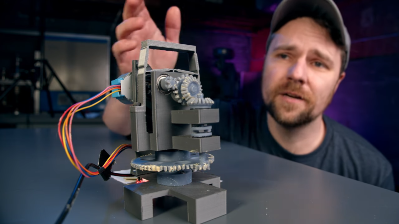
We end up covering a lot of space topics here on Hackaday, not because we’re huge space nerds — spoiler alert: we are — but because when you’ve got an effectively unlimited budget and a remit to make something that cannot fail, awe-inspiring engineering is often the result. The mirror actuators on the James Webb Space Telescope are a perfect example of this extreme engineering, and to understand how they work a little better, [Zachary Tong] built a working model of these amazing machines.
The main mirror of the JWST is made of 18 separate hexagonal sections, the position of each which must be finely tuned to make a perfect reflector. Each mirror has seven actuators that move it through seven degrees of freedom — the usual six that a Stewart platform mechanism provides, plus the ability to deform the mirror’s curvature slightly. [Zach]’s model actuator is reverse-engineered from public information (PDF) made available by the mirror contractor, Ball Aerospace. While the OEM part is made from the usual space-rated alloys and materials, the model is 3D printed and powered by a cheap stepper motor.
That simplicity belies the ingenious mechanism revealed by the model. The actuators allow for both coarse and fine adjustments over a wide range of travel. A clever tumbler mechanism means that only one motor is needed for both fine and coarse adjustments, and a flexure mechanism is used to make the fine adjustments even finer — a step size of only 8 nanometers!
Hats off to [Zach] for digging into this for us, and for making all his files available in case you want to print your own. You may not be building a space observatory anytime soon, but there’s plenty about these mechanisms that can inform your designs.
Thanks to [Zane Atkins] for the tip.


Brilliant video.
After watching it I would guess that testing all 108 stepper motors (18 mirror segments with 6 single point of failure stepper motors per mirror) was a high priority test.
Sorry 132 motors in total even, 108 motors to adjust the position of the 18 primary mirrors, 18 additional motors to change the ROC (radius of curvature) of the 18 primary mirrors, and then another 6 motors to adjust the position for the secondary mirror
Definitely! There’s a followup paper from 2012 where they go in-depth on failure testing and analysis [1]. Interestingly the main source of failure was the bearings and dry lubricant, which failed well before anything else including material strain of the flexures. So the design was roughly finalized in 2006, but the gearmotor kept undergoing tweaks and changes up until about 2012 to address lifetime issues.
Even with those changes, the motors are only rated for a certain number of revolutions before probable failure, so the JWST team is apparently keeping track of how many revs each motor has done. Neat stuff!
[1] https://www.spiedigitallibrary.org/conference-proceedings-of-spie/8442/1/Actuator-usage-and-fault-tolerance-of-the-James-Webb-Space/10.1117/12.924596.short?SSO=1
[1b] Scihub version: https://sci-hub.se/10.1117/12.924596
Wow, a Sci-Hub link. I’ve never seen one of those here on HaD.
Brilliant, I wonder if the mechanism could be used for the movement platform of a simple laser scanning microscope. I’ve been wanting to build one for some time now, but haven’t gotten to it yet. Originally I was planning on driving a small speaker and using the movement for the platform, but this seems much more practical.
Check out https://openflexure.org/projects/microscope/
It would have been in interesting demonstration if he glued a small mirror to it and bounces a small laser beam onto a wall.
Remember that this is only 1/6 actuators needed for the Stewart mechanism. This will only give axial displacement.
Ball has clearly borrowed an idea from the combination lock, use of the word “tumbler” is a hint.
Indeed. As a child I had a toy combination safe that had the same mechanism in it. It was a two-number combination safe in which the mechanism was exposed once the save was open. There were two wheels, the first with a drive pin that caught on the second wheel, just as in this actuator.
this idea is a common mechanism, by far nothing new or unique.
I’ve not looked at the actual Ball design but there’s loads of backlash with all those gears and leadscrew. Even using anti-backlash gearing. And there’s tooth-tooth variation in the gears. This needs super precision manufacturing. Not fun at all and quite slow with all those reductions, not that it’s an issue for the intended use. Also, the whole thing runs at near zero K. No lubricants and frozen steppers. Not surprising that it took 30 years.
The beauty of Ball’s design is that the high-precision part is based on a cam and material flexure, not screw/worm gearing. Only the coarse positioning depends on a lead screw. While I’m quite sure that every part was manufactured to impeccable tolerances for this application, the elegance of the design is that such high tolerance isn’t strictly necessary for proper functioning of the fine adjustment mechanism.
Backlash is only a problem when you change direction. If you always overshoot your target from one specific direction, and correct it from the other direction then it’s a non-issue.
Anyway, it works, so they’ve probably dealt with your concerns. It’s not exactly rocket science.
Fascinating.
I didn’t know that the company that makes Mason jars also had an aerospace division!
Good catch. But… :-) Ball sold the glass jar division to Crown Cork and Seal quite a few years ago. They were also the Ball Brothers of computer monitor fame. I don’t think the TRS-80 model 3 and 4 necessarily used a BB monitor assembly but the analog board edge connector used the then-“standard” BB pinout. Separate video, H-sync, and V-sync at 15.575 KHz.
Hazeltine did use a BB monitor assembly in either or both of the 1500 and/or 2500 terminals. I had one, but I can’t remember the model. Probably weighed 50 pounds – the terminal, not just the monitor.
Ball did some significant chunks of Spirit and Opportunity. They also do a good-sized classified business, or at least they say they do. :-)
IIRC, the deformable mirror/adaptive optics were originally developed for use in spy satellites, thus the Hazeltine and Ball legacy. You could better read “licence plate numbers” if your satellite optics could compensate for atmospheric distortion. The idea was then used in ground based telescopes to better see “the other direction” through the atmosphere, with the use of laser “artifical stars”.
But I may be wrong about all this…
How do you compensate for atmospheric distortion when it’s whipping by underneath you at 7 km/s?
During the Cold War the DoD looked in using adaptive optics (first theorized by astronomer Horace Babcock in 1953) to get a clearer view of Soviet satellites *from the ground*.
The DoD also considered using the technique to correct for atmospheric beam distortion of ground-based laser weapons, but abandoned the effort as the technology simply wasn’t there yet.
In neither case did they consider applying it to spy satellites for the very reason you implied: the optical path would change *much* too quickly for AO to compensate. Even today the correction rate needed (in the MHz) for ground-looking spaceborne platforms is still well out-of-reach. Meanwhile the best optical telescopes (Magellan, et al) correct at ‘only’ around one kilohertz, max.
It’s a clever design, but seems like an awful lot of trouble and complexity to re-use a single motor for both fine and coarse purposes. You’d gain some redundancy, increase motor life, and likely *reduce* total mass by using a second motor.
The “fine” stage is only 8 times more precise. You’d think the complexity could be reduced a lot by just using a single mechanism, and just run the motor a bit longer. It’s not like you need the speed: in “coarse” mode, the mirror can move end-to-end in a few minutes. Even in “fine” mode step size, it could traverse the whole 20mm in under an hour.
The coarse-fine mechanism does have the advantage of use a flexure for fine adjust, but not requiring the flexure to accommodate the whole 20 mm travel.
I still think the 2-motor solution would be simpler and more reliable.
The hubris here, thinking you know better than dozens of engineers at both NASA and a company that has been doing this sort of thing for decades, is truly breathtaking.
Here’s some reading material for you. https://www.dannyguo.com/blog/my-seatbelt-rule-for-judgment/
That’s a good read. Thanks.
I think you absolutely hit it on the head about the coarse/fine: “not requiring the flexure to accommodate the whole 20 mm travel.” I imagine in the NASA version of this device, it’s made of aluminum or Fancy Space Metal. Metal _is_ flexible, just over very short extents — otherwise it fatigues and snaps.
They probably also have their reasons for preferring a mechanical setup over a second motor. Wiring, control logic, weight, reliability?
My (wild-ass) guess is that what to you looks like redundancy, to NASA looks like 6*16 additional points of failure. Testing the lifespan of this mechanical device is easy because it’s comparatively simple. I wonder what their model for the reliability of a motor is like.
Yeah, I suspect they wanted to limit the number of motors because they were the main source of failure (ala Barto, A., et al 2012). The bearings and dry lubricant underwent a lot of revisions and was still the ultimate source of failure. So introducing twice as many motors was probably rolling more dice than they liked.
It’s important to note that a second motor isn’t redundancy in this case, it’s a liability. If either the coarse or fine stage motor died, the mirror segment is just as hosed as if there was a single motor. And since they are the probable failure mode, you would want to minimize the number of motors.
And that’s ignoring all the other aspects like trying to design a flexure that can move 20mm (you won’t be able to do it in such a small package, flexures are _always_ many times larger than their travel range), reducing weight, reducing electrical complexity and heat output, needing to gear up the coarse motor just as much as the fine, etc etc.
You are only thinking of complexity for one component(actuator assembly, 1 of over 100) of the whole system(JWST), you also have electrical(physical number of wires and driver components), computational, and then power requirements, failure points, etc.
I did not find what are those flexures made of. What is flexible in such low temperature and immune to the fatigue?
TFA says it’s made of EDM’d titanium.
I still do not understand how the coarse movement can achieve 20mm. The torsional stabilizer does not look that it could allow that 20mm movement. I would like to see some animation of that long movement.
The actual design documentation was not release, just a rough idea of how it was designed.
So the 3d printed parts used in the video are really only approximations.
Wow, I do not believe that I missed this when it first came out but what a brilliant idea for an adjustment, as long and the fine segment has at least the span of one course adjustment. I am assuming like in many things you are adjusting for the peak, and you could dial the course, watch the peak rise and move forward until one tick past the peak, and know that the peak will now be within the realm of the fine adjustment going the other way. The fine may have to overshoot it by one tick, but it would be a tiny tick, or remember how many ticks in the peak was at, go back and take the course adjustment back one, go back into the fine and stop at that many ticks. Very cool, and interesting. I wonder how long it would take to get used to on something like the tuning dial on a ham radio. Even neater would be on the dial a button that would have 3 positions, one perhaps spring loaded, to press the driven pin into the drive pin for the course. The second position to let the pin float, exactly like in the model, and a third, all the way out, so you only have the fine. Kind of a course, auto, and fine setting on the knob.