Sometimes you notice something small that nevertheless you can’t explain. [Greg Davill] found himself in just such a situation this week when he noticed some green LEDs glowing dimly when reflowing some boards. Naturally, [Greg] set out to investigate.
The green LEDs were wired up as power indicators, and [Greg] suspected that the polymer caps on the board might be generating a small current somehow that was causing the LEDs to light up ever so slightly. A simple test hooked a polymer cap directly up to a multimeter. When warmed with a heat gun, the meter showed a small current “in the 5-10 uA range.”
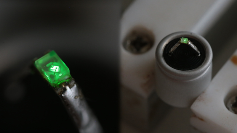
Going further, [Greg] soldered an LED to the cap and once again heated it up, this time to 100° C. The LED glowed, continuing to do so for around 60 seconds with heat removed. The mystery also grew deeper – [Greg] noticed that this only happened with “fresh” capacitors. Once they’d been through one heat cycle, the caps would no longer light an LED when warmed up.
It’s a curious case, and has many speculating as to the causative mechanism on Twitter. Explanations from thermoelectric effects to chemical reactions inside the capacitor. If you’ve got the inside scoop on what’s going on here, don’t hesitate to let us know in the comments. Meanwhile, check out some of [Greg]’s best work – a glowing D20 dice featuring a whopping 2400 LEDs.
[Thanks to J Peterson for the tip!]


That’s the magic smoke breaking in!
I wonder whoever first makes this a feature (pcb testing during reflow? self-powered reflow?)
a test for scavenged parts…
eventually some effekt of charge fluffing caused by heat. somerimes you can see this effekt by capacitors based on piezobased ceramics, if you heat a polarised cap above a special material temperature, then the cap materials will start zo depolarise – as in this polarisation also energy is stored ( like kinetic energy ) . if you connect a scope the cap with the classic 1M resistance you will see a voltage peak. Dependent on temperature and material it could happend that the cap is minimal or max depolarised – which has influence of the capacity……. i have no experience with this with polymerbased caps, but naturally the polymerbased materials have lower temp for this effect.
I had used this in past this to turn unpolarised X/R caps to force sensor by polarisation with higher voltage and temperatue. Background was to get an information for failure analysys (because of broken caps) about force distribution on a large pcb. Also the mechanical conditions must be original, because of this i couldnt use the smallest sensor which you can buy.
As all in the nature nothing is not only one – everywhere you have multiple influences, so a cap is not only a cap it could also sense fore or noise and generate also microvibrations with could be seen and genereate noise in other components. Mosten time this is’nt seen – but sometimes it is good to look a little bit deeper.
Interesting question Levin thank you very much- could you test the capacity of the cap before / after heating….
Would be interested if you see a change in capacity after heating…..
My bet would be on something oxidising.
seems plausible.
I’d try some tests to (maybe) narrow it down:
1. fresh cap – charge profile when connected to ~max rated DC.
2. more charge profiles of same cap after 1.
3. 1.+2. after cap has been heated (and cooled down again).
4. 1.+2. and heat the cap afterwards (with led and measure power profile).
It could be the pyroelectric effect in the dielectric. Just like piezoelectric effect, where a change in strain causes a charge shift, the pyroelectric effect shifts charge with a change in temperature. A well-known effect. I’m surprised it didn’t pop up in the twitter comments.
Not sure why it is a one-shot though. Maybe there’s a relaxation effect going on too, relieving the strain caused during manufacturing.
it reminds me of glass tubes that burn the getter on first usage to pull a vacuum, though i don’t see how it could be related.
Most likely this. The high-permittivity ceramics used in MLCC caps are typically perovskites (e.g. doped BaTiO3) that can exhibit all kinds of nonlinear effects that you can see in C(V) and C(T) behavior. Piezo- and pyroelectricity goes hand in hand.
From a quick skim it appears that X7R, one ceramics used, is partially ferroelectric. Ferroelectrics exhibit a built-in polarization that is lost when the material is heated above a certain temperature, the curie temperature, and gained again during cooling. This should create a current when the capacitor is heated and cooled.
There is an explanation
https://ec.kemet.com/blog/mlcc-dielectric-differences/
Ok, taking a second look at the image on top, it appears that this is an eletrolytic cap. So no ceramics present and the explanation is void.
“… this only happened with “fresh” capacitors. Once they’d been through one heat cycle, the caps would no longer light an LED when warmed up.”
Makes me wonder if the caps performance or value was altered during the heating process. Are they even still in spec? Could this be what led to those Chinese caps used in laptops and motherboards blowing up a long time ago?
Components are designed (and specified) to go through these processes, it’s not a problem.
The bad cap plague was entirely due to defective electrolyte being used during manufacturing. Claims have been made that the electrolyte was made using an incorrect/incomplete formula stolen from RubyCon and then used by several cheap Chinese and subsequently Taiwanese factories.
Too bad Hack-a-day doesn’t have a simple Reddit-like up vote or like function. Consider your reply +1. I often wondered what caused them to blow up.
No Voting here! The moment you introduce up/down voting the whole place turns into a political hate-fest. Go look at Ars to see how it will turn out.
Don’t need to look at Ars. Just look at what a pile reddit is.
I wonder how much electricity the LEDs make under the infrared light of the oven.
FYI, the green leds are REALLY sensitive. Or actually “quite efficient” and the human eye is phenomenal.
Under normal circumstances as an indicator light, I design PCBs to send about 27mirco-amps through these leds. So 5-10 microamps can certainly be seen.
I also tested donw to what current the led can be seen working…. In a darkened room you can see them down to about 50 nano amps. Almost a million times less than the max!
Tell that to Arduino designers, who add green LEDs to battery powered MKR boards, that suck up 10 mA and cannot be turned off.
The “An indicator LED needs 10 mA” is one of these pesky design practices that really needs to disappear…
LEDs don’t need much current, and they do survive a drastically longer time if one don’t push a lot of current through them. And for an indicator that in itself is a valuable feature.
I though normally decide by eye what current is decent for a certain LED. But usually a 3k3 or 5k resistor on 5 volt is good enough for indicators, almost regardless of what LED one uses. (though, some blue ones are still a bit on the “too bright” side.)
Yes, but too little current may stop working after a few days. I’ve had indicator LEDs stop working with 70 uA and had to boost it to 100 uA for it to be reliable after deployment.
Induction from the heating coils with led (diode) charging charging cap on half cycle?
Which heating coils?
Big capacitors gather charge from static; if your bank is in an outdoor shed you might notice it gathers more on windy and cold days, too. Could that be part of this? if so i’d think it’d be repeatable.
What if the capacitor was already charged and just discharged because of the heat?
I think that’s the most logic conclusion since he could do it only once.
Perhaps recharging the capacitor will yeald the same effect afterwards.
Caps are aged in at voltage in the factory, this causes semi-permanent polarization of the dielectric which lowers the usable capacitance. Heating the dielectric above its curie temperature resets this effect and improves the capacitance (until it ages in again). When the dielectric depolarizes the charge trapped inside is released and causes current flow.
Similarly, if you wrap a magnet in copper wire and then heat it above its curie temperature it will induce current in the coil when the magnetic field is neutralized. If you do this rapidly (with say, high explosives) current pulses of many thousands of amps can be produced with nanosecond rise times.
Interesting! This explains why it is polarized in one direction. Otherwise I would have expected that the polarization cancels and there is no preferred direction. (Unless you pre-strain your ceramics or something)
I think what we are witnessing here is some sort of Peltier effect. With Peltier’s, you have two different types of material that react thermally when voltage is applied to them. Making one side hot, and the other cold. They are used extensively in some desktop fridges and coolers.
On the other side of this effect, if you heat up one side, a small voltage is induced, the more heat, the higher the voltage. I’ve used this effect to run a fan at certain temps. I think we are seeing this effect happen in new caps. The heat is inducing voltage across the two different Dielectric materials.
Agree with that theory. Would be Seebeck effect (reverse of the Peltier effect), creating a potential difference on the semiconductor junction of the LED, enough to emit some light.
https://en.wikipedia.org/wiki/Thermoelectric_effect#Seebeck_effect
“Seebeck” THAT’S the word I was looking for! Thanks!
I’ve noticed in the past with a piece of cheap white12V led tape that I can get the leds to glow very faintly just by pressing my fingers on the gaps between them. It works whether they are plugged in or not. I assume it’s stray something but my electronics knowledge isn’t good enough to make a better guess.
Infrared light??
This is a known phenomenon.
If a capacitor is charged and then discharged quickly, it will regain some of its voltage. This is known as “recovery voltage”.
Even when discharged completely, heating will cause voltage to rise again through the same mechanism.
If I remember right, some university managed to get the recovery voltage almost back to the charged voltage through heating.
I remember reading this a long time ago in either “the art of electronics” or “troubleshooting analog circuits”. Likely the latter, but I couldn’t say for certain.
It is possible that you have a “leaky” solder iron that is charging a cap on the board. If your iron is not properly grounded, you can easily insert current into a circuit when soldering.
Nope!
I don’t think it is the capacitor, as I have seen the same effect while I was soldering LEDs by hand with my soldering iron, and there was no capacitor involved in the circuit
But I never found out why (I suspected it could be the iron that was leaking some kind of current)
I have seen this too, soldering LED’s on a PCB with no caps (yet).
I suspect the iron too. It’s a Pinecil driven by an USB-C PD supply.