All things considered, it’s pretty easy to get one LED is a strip to light up sequentially, and have it bounce back and forth. Turning that simple animation into a real Larson scanner, with smooth transitions and controlled fade-out, is another thing entirely. And forgetting the LEDs altogether and making a servo-operated Larson scanner is — well, let’s just call it an interesting lesson in hardware abstraction.
The Larson scanner, named after famed TV producer Glen A. Larson for his penchant for incorporating it into shows like Battlestar Galactica and Knight Rider, is actually hard to execute in hardware thanks to the fading tail that follows the lead pixel as it dances back and forth across the display. [Eric Gunnerson] decided to make this and other animation effects easier to achieve with Fade, a custom framework for LED animations that runs on an ESP32.
LED animations are fine, but what about servos? Could Fade be modified to support them? This turned out to be a fairly easy mod thanks to Fade’s architecture and [Eric]’s existing support for non-addressable LEDs via PWM signals. And it was even possible to support more than the 16 PWM channels on an ESP32by adding a UDP connection that puts multiple ESP32s under the control of a central microcontroller.
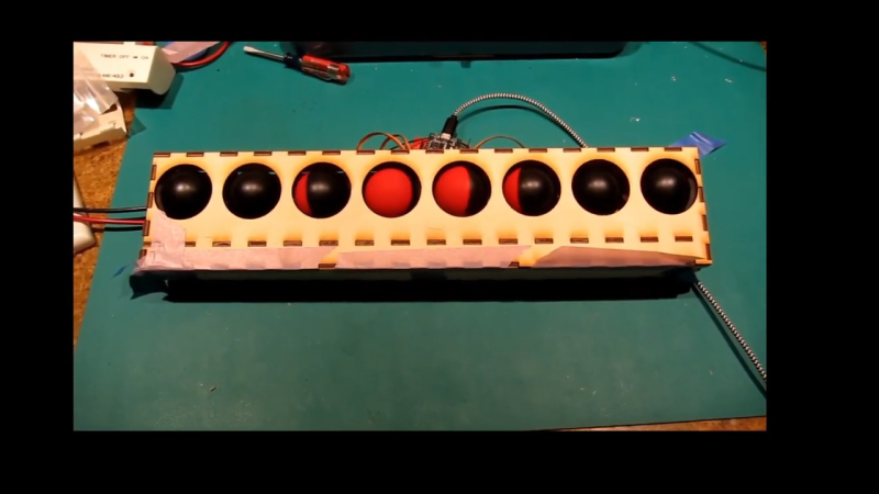
The video below shows [Eric]’s demo of servo support, with an eight-channel electromechanical Larson scanner. Each “pixel” is a painted ping pong ball swinging back and forth on a hobby servo, and the whole thing sounds just about as awful as you’d expect it to. If you squint just right, the effect looks pretty convincing, but that’s hardly the point. The real story here is [Eric]’s thoughtful architecture, which made the mods easier than starting from scratch.


A slight improvement would be if the redness could fade out from either the left side or the right side. This would make the animation a bit more symmetric.
Yep. That’s would improve things a lot.
Maybe shading the balls?
Would be a big improvement but it would require continuous-revolution servos and they work differently.
For arbitrary rotations from either side, it would need continuous rotation, but for this purpose, you could get away with just gearing the servo output to provide 360 degree rotation, since the motion reverses with each pass.
If you go with continuous rotation, steppers motors (with a zero sensor) would be better and quieter than common servos.
Go for it. I shall look forward to your project write-up.
Servos were not a good choice for the simple fact that they are noisy and complicated. Using electromagnetism directly would ensure it’s perfectly silent though it could still be quiet (but not silent) as a purely mechanical device.
Probably harder to get a smooth fade then, which was the main goal of the project.
If we’re putting forward completely different ways to build a mechanical Larson scanner, those linear PCB motors would do it. Or a stepper motor with a red card on a timing belt :)
A moving coil meter movement makes nice smooth motion – just need to scale it up to have sufficient current to move the ball.
Yep, nobody would have taken the Cylons if they sounded like that.
By your command…
The whole reason I did the project was to demo the servo support in fade.
What do you mean by “using electromagnetism directly?”
Magnetic flip dot display. Vary the current to the coils and they can be flipped to varying degrees.
Magnetic flip dot displays are bistable. They can’t “be flipped to varying degrees.”
Using the PWM to drive a moving-coil meter (suggested above) would work, though.
That’s a perfect use for that box of old WW-II panel meters in the basement. The ping pong balls can be attached to the meter movements.
Neat. All my Larsons are in storage. I should scan them before the fade away!
You can use a continuous belt with the red part painted on. Use 2 limit switches that trips on both ends that goes to a RS flip/flop to drive a relay to change motor direction. You can use the R/S flip/flop in a *555*. :P
I don’t think that actually works. You may not be able to tell in the video, but in a larson scanner you get a lot of red at the leading part with it fading out in the trailing part. That means the pattern looks different going left than it does going right.
Great point. Guess you’d have to use some sort of flexible gradient flag that drags behind the main movement
Transparent belt
Instead of saying thing won’t work in multiple ideas, WHY don’t you think of ways to make things works for a change?
You realize that the dot can be symmetrical, right?
Your definition of larson scanner is a bit too straight. I grew up watching Knight rider and Battlestar Galactica.
If you have a LED light on the belt and a fluorescent screen that has a short time constant, then there will be a bright light followed by a fading trail.
Your lack of imagination does not imply things won’t work.
1 DC gear motor, 2 limit switches, and a current reversing relay. Each ball offset by 45 degrees to its neighbor, and all balls geared to turn together.
Won’t be any quieter, but the noise might be more pleasant, and the effect will be much better.
Doesn’t really serve his purpose, but what the heck.
Don’t think that works, as the pattern is not symmetrical. The leading spot is always the reddest with those trailing becoming less red. When you switch directions the relationship flips around.
And you might have cases where the redness is 25% 100% 75%
It doesn’t work perfectly but it’s close enough – I’m sure with some clever linkages you could make the whole thing work perfectly from a single DC motor in a continuous rotation.
“actually hard to execute in hardware”?
Over 30 years ago I made one out of hardware (not servos though) and it was super simple.
A 4011 quad 2-input NAND as a low frequency square wave oscillator with a potentiometer to adjust the speed.
This fed the clock of a 4017 decade counter where the outputs each fed a transistor to turn a LED on. A simple capacitor made the LED fade when the transistor turned off.
There were 6 LED’s and output 7 fed back into LED 5, 8 into 4 etc. to make the trail snake from left to right to left…..
analog approach:
LM3914 bar graph in dot mode with a triangular wave + a small AC bias to “spread” it across multiple LED.
The Data General Eclipse computers had old-school front-panel LEDs for address and data as well as switches for front panel hacking. There was a ‘Cylon patch’ available for the OS that would show this. It was very cool! IIIRC, it also indicated system load by the scanning speed.
The scanning panel lights in the address register display was a thing on Digital PDPs running the RSX operating system. I don’t think the RT-11 operating system ever inherently supported the feature. I believe the older PDPs had cartridge type 5 Volt lamps.
The PDP 11/34 I used at work had boot ROMs, hardware initial jump, and a seven segment LED display. There was no toggle switch gymnastics to enter the jump address and data, or nifty lights to watch while pondering FORTRAN statements at the ASR-33 TTY.