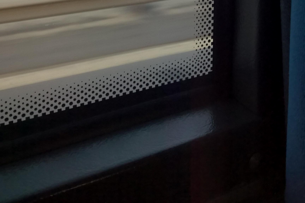
Servo Larson scanner

No LEDs Required For This Servo-Controlled Larson Scanner

All things considered, it’s pretty easy to get one LED is a strip to light up sequentially, and have it bounce back and forth. Turning that simple animation into a real Larson scanner, with smooth transitions and controlled fade-out, is another thing entirely. And forgetting the LEDs altogether and making a servo-operated Larson scanner is — well, let’s just call it an interesting lesson in hardware abstraction.

The Larson scanner, named after famed TV producer Glen A. Larson for his penchant for incorporating it into shows like Battlestar Galactica and Knight Rider, is actually hard to execute in hardware thanks to the fading tail that follows the lead pixel as it dances back and forth across the display. [Eric Gunnerson] decided to make this and other animation effects easier to achieve with Fade, a custom framework for LED animations that runs on an ESP32.

LED animations are fine, but what about servos? Could Fade be modified to support them? This turned out to be a fairly easy mod thanks to Fade’s architecture and [Eric]’s existing support for non-addressable LEDs via PWM signals. And it was even possible to support more than the 16 PWM channels on an ESP32by adding a UDP connection that puts multiple ESP32s under the control of a central microcontroller.

The video below shows [Eric]’s demo of servo support, with an eight-channel electromechanical Larson scanner. Each “pixel” is a painted ping pong ball swinging back and forth on a hobby servo, and the whole thing sounds just about as awful as you’d expect it to. If you squint just right, the effect looks pretty convincing, but that’s hardly the point. The real story here is [Eric]’s thoughtful architecture, which made the mods easier than starting from scratch.

Continue reading “No LEDs Required For This Servo-Controlled Larson Scanner”

Software Pulse Width Modulation

daqq_pwm_schematic

Pulse Width Modulation is a topic that tends to give a lot of beginners trouble. [Daqq], whose nixie plasma ball we covered a few days ago, has a simple but effective PWM project that you should take a look at. The circuit used 9 LEDs clustered together into 3 sets of RGB modules and connected them to an AVR ATtiny2313 through some current limiting resistors. Most of the time the PWM function of the AVR’s timers would be used to generate the signal but this application calls for 9 signals which is more than can be produced by this chip. The workaround is to generate the signals using software PWM. Continue reading “Software Pulse Width Modulation”