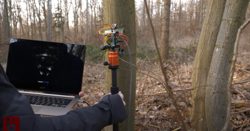
Ultrasonic transducers are incredible, with them you can detect distances, as well as levitate and peer through objects. They can emit and receive ultrasonic soundwaves (typically above 18khz) and just like all waves, they can be steered via a phased array. [Bitluni] was trying to accurately measure distances but found the large field of view of the sensor was just too imprecise, so he made a phased array of transducers.
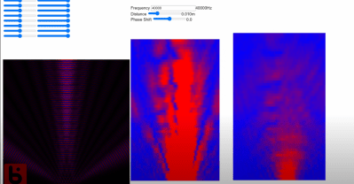
The inspiration came from a Hackaday Supercon talk from 2019 about phased arrays. [Bitluni] walks through an excellent explanation of how the array works with a bucket of water and his finger, as well as a separate simulation. By changing the phase offset of the different array members, the beam can effectively be steered as interference muffs the undesired waves. Using a set of solenoids, he created a test bench to validate his idea in a medium he could see; water. The solenoids fire a single pulse into the water creating a wave. You can see the wave move in the correct direction in the water, which validates the concept. A simple PCB sent off to a fab house with a stencil offers a surface to solder the transducers and drivers onto. An ESP32 drives the 8 PWM signals that go to the transmitters and reads in the single receiver via a small amplifier. Still not content to let the idea be unproven, he sets up the receiver on his CNC gantry and plots the signal strength at different points, yielding beautiful “heat maps.”
It sweeps a 60-degree field in front of it at around 1-3 frames per second. As you might imagine, turning sound wave reflections into distance fields is a somewhat noisy affair. He projects the sonar display on top of what we can see in the camera and it is fun to see the blobs line up in the correct spot.
We noticed he built quite a few boards, perhaps in the future, he will scale it up like this 100 transducer array? Video after the break.


“A simple PCB sent off to a fab house with a stencil offers a surface to solder the transducers and drivers onto.”
Wow, just wow…
I watched the video. I didn’t see that part though. There’s a sponsored part for a PCB fabrication service, but he still didn’t say that. He solders the PCBs right in the video.
The quote comes from the second paragraph in the article
Nice work ! He created a small near field range to calibrate the sensors though I wonder how he accounted for echos in his 3D printer NFR.
I’ve looked into doing similar work years ago to create a low cost tow fish to scan a lake for bottom topography. I became disillusioned with the idea as I learned each sensor/transducer is a highly tuned resonant device, more tuning fork than speaker. The phase slope of anything resonance is at its greatest at resonance. With each device being slightly mistuned wrt the others, that’s a mess to straighten out. So calibration in a NFR to the rescue (like we do with radars)? Perhaps but what happens when the resonant frequency shifts due to temperature, loading, aging, etc. With sharp slopes just a little will mess up the beamforming. I wonder how well the array in the OP held up in this regard?
Amazing proof of concept!
It would be great to see this compared to a broad band transducer that is rotated and use synthetic aperture methods.
Next step: Use one of the purpose-made driver ICs to drive all those elements more easily (st.com makes a bunch of them).
Then: Use the same elements to do phased-array receive too, dispense with the oddball single receiver element, and get better images.
Transmit/receive switches are easy to do in a number of ways: either discrete diodes, cmos switches, or purpose-built ICs.
You can digitize a single element at a time with an analog switch to select each one, but multi-channel simultaneous ADCs are readily available too.