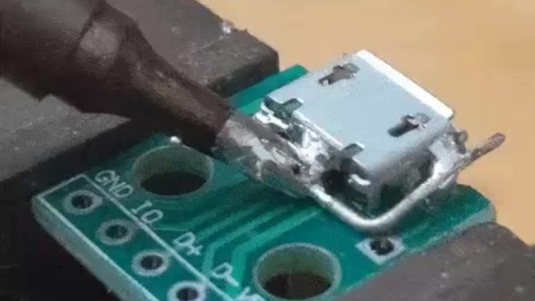
Quite a few hackers nowadays share their tips and tricks on Twitter – it’s easy to do so, and provided either an existing audience or a bit of effort to get one, you’ll get at least a few notifications telling you that people appreciated what you had to share. Today, we’re covering two desoldering hacks highlighted there that will be useful some day, exactly when you need them. Both of them use a piece of wire and, in a way, extend the reach of your soldering iron’s tip. Copper wire would work better because of superior thermal conductivity, but other types of solid core wire will work in a pinch.
First hack is brought to us by [Erin Rose] – desoldering a microUSB socket. You need to heat up the entire shield and the pins at the same time, which the wire acts as a thermal gateway for. As long as there are melted solder bridges from sections of the wire to all the copper-to-part connection points, it should be easy to pump enough heat into the solder joints for all of them to eventually melt and give in at once.
Second hack is brought to us by [arturo182]. A piece of thick wire acts, again, as a heat conductor to desolder a 0.5mm pitch TQFP-100 package IC. You have to bend the wire into a correct shape, so that it’s as close to the pins of the TQFP as possible. In this situation, the wire performs two functions: first, transferring the heat from the iron’s tip to different points along the wire, then, as a barrier that helps solder not escape too far away from the pins. Copious amounts of flux likely desired for this one!
Hopefully, this comes handy if you ever need to replace an all-SMD part ASAP but don’t have a hot air gun or a hotplate handy. After getting this concept down to an art, we are sure you won’t limit yourself to TQFP parts and MicroUSB sockets. We’ve talked about desoldering practices before as part of our newsletter, and using lots of melted solder for part removal is not a foreign concept to us, either.
An interesting technique for desoldering QFP without hot air! pic.twitter.com/50ynzkrJXb
— arturo182 (@arturo182) January 2, 2021


My solution is mixing in some tin-lead solder that drops the melting point. Then wick away what I can, especially on the through-hole feet. And plentiful flux. That way there’s a lot less thermal mass to overcome. But obviously whenever possible I use a hot plate for pre-heat and hot air.
I’ll have to add these hacks to my toolbox, but I think I still prefer Chip Quik alloy–less likely to overheat parts or lift pads/traces.
Be careful with the bismuth based low temp solders. They aren’t a cure-all, and longevity can be a problem.
To be clear, Chip Quik should only be used to remove parts. After removing the part, thoroughly clean the Chip Quik off the board and solder the new part with the proper solder.
I wonder if there are studies of long term side-effects of the bismuth leaching into the pad and contaminating the new solder through diffusion. It’d probably be such a small amount, but no matter how well you clean it will still be there and could have an undesirable effect on things like whisker growth or mechanical strength.
I used to use a lot of solder and a flat head screwdriver and heat up one side by dragging the iron back and forth, using the screw driver to lift one side, then the other. Usually this also kept the pads in tact if you apply just enough force to bend one side of the chip off the pcb. Cleanup solder and bend back the chip pins and it’s ready for re-use. Only works on dual in line chips of course. With qfp packages it is impossible using this trick.
I now have a pre-heater and hot air, and if there are connectors on the pcb I can use low melt solder (4.50 euros for 17cm wire) or heat the pcb from the bottom, which may result in burn marks.
The method in this article needs an iron than can transfer a significant amount of heat into the copper wire. And you’ll need a lot of solder to bridge the gaps between copper and pins and a way to keep the copper wire in place at the same time. It works by increasing mass to increase heat capacity so you can heat up different areas at the same time, but you still need to go around with the iron to get everything up to temperature, especially with pcbs with large copper planes. The longer the chip is heated the higher the chance of damage to the pcb and the chip (ie to de-solder a chip from a donor board).
Why not use desoldering braid for this?
@geolemon said: “Why not use desoldering braid for this?”
Esily lifted pads is one good reason.
Not rigid enough