The Core Duo processor from Intel may not have been the first multi-core processor available to consumers, but it was arguably the one that brought it to the masses. Unfortunately, the first Core Duo chips were limited to 32-bit at a time when the industry was shifting toward 64-bit. The Core 2 Duo eventually filled this gap, and [dosdude1] recently completed an upgrade to a Macbook Pro that he had always wanted to do by replacing the Core Duo processor it had originally with a Core 2 Duo from a dead motherboard.
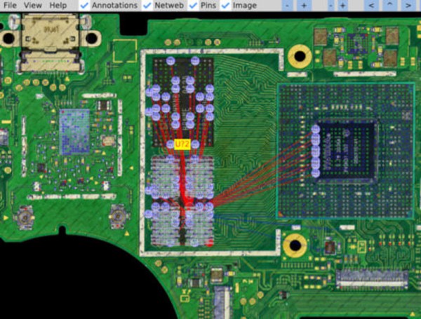
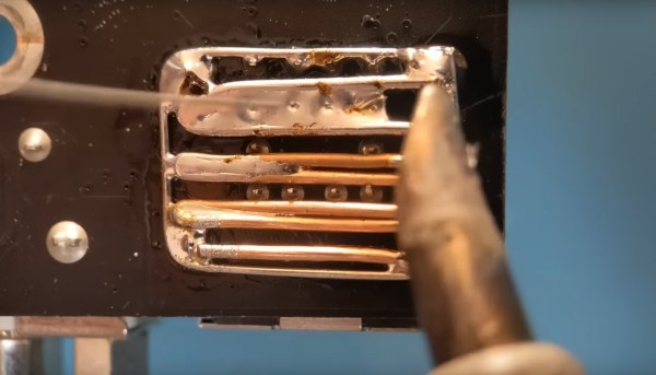
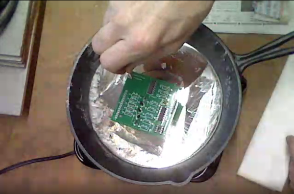
The upgrade does require a bit more tooling than many of us may have access too, but the process isn’t completely out of reach, and centers around desoldering the donor processor and making sure the new motherboard gets heated appropriately when removing the old chip and installing the new one. These motherboards had an issue of moisture ingress which adds a pre-heating step that had been the cause of [dosdude1]’s failures in previous attempts. But with the new chip cleaned up, prepared with solder balls, and placed on the new motherboard it was ready to solder into its new home.
Upon booting the upgraded machine, the only hiccup seemed to be that the system isn’t correctly identifying the clock speed. A firmware update solved this problem, though, and the machine is ready for use. For those who may be wondering why one would do something like this given the obsolete hardware, we’d note that beyond the satisfaction of doing it for its own sake these older Macbooks are among the few machines that can run free and open firmware, and also that Macbooks that are a decade or older can easily make excellent Linux machines even given their hardware limitations.
Continue reading “Upgrading An Old Macbook With An Old Processor”