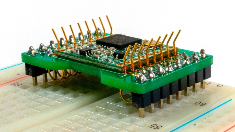
[SolderParty] just announced FlexyPins (Twitter, alternative view) – bent springy clips that let you connect modules with castellated pins. With such clips, you can quickly connect and disconnect any castellated module, swapping them without soldering as you’re prototyping, testing things out, or pre-flashing modules before assembly. They’re reportedly gold-plated, and a pack of ~100 will set you back 6EUR, shipping not included.
Of course, this is basically “fancy pieces of wire”, purpose-shaped, gold-plated and, hopefully, made out of material that is springy enough and doesn’t snap easily after bending a few times. We’ve seen this concept used for prototyping before, with random pieces of wire doing a pretty good job of maintaining connectivity, but these clips bring it that much closer to production-grade. It also makes us wonder – just how hard it is to solder 30-40 of them into a circuit? Do they self-align enough with the footprints given, or do you have to hold them with tweezers at a peculiar angle as you solder them? Time will tell, of course.
Don’t expect to see them used in regular circuits, as they’re quite space-consuming. However, for those of us prototyping and manufacturing, this is one more tool in our arsenal, and we’ve already seen some fun uses for these. They could also be pretty useful for experimenting with firmware of proprietary castellated modules, letting you reuse the same development board between different modules as you tweak things. And, if you’re like us and got a drawer with dead NodeMCU ESP32 boards, having a springy breakout for testing ESP32 modules might come in handy.
You can likely make such pins yourself – we’ve reviewed this principle before, with a nice 3D-printed jig to match! Flashing and testing castellated modules before soldering them seems to be a popular scenario, and for the aforementioned ESP8266 alone, we’ve reviewed quite a few testing and flashing jigs – check out this 3D-printable one, or this Wemos-board-turned-pogopin-jig one!
We thank [Chaos] and [adrien] for sharing this with us!


That there is honestly a very nice looking interface to be fair.
Wouldn’t be particularly hard to make such springs with a 3d printed jig. Though, the gold plated nature might be harder to trivially replicate, unless one has gold plated wire on hand…
Gold plating isn’t impossible for the home enthusiast, probably not worth it though – and have to ask if its worth it here. It seems rather unnecessary – unless the wires themselves are some form of really poorly conducting spring steel or something underneath (which is probably a good idea if you really want many many cycles and accident proof durability, but I expect boring old copper would do nicely and be cheaper) then just leaving them uncoated aught to do a perfectly adequate job on such a large contact area, at least for most situations these sort of board mounts are used for.
I think the main value of them is that using high quality conductors removes one more variable for you to worry about when troubleshooting. Back in the day we used to have to spray Deoxit and other, less pleasant to use products, on all manner of connectors. Now, not so much, thanks to special tip coatings, gold plating of connections, etc. For less than a tenner you get multiple sets of pins to produce a jig in any size and shape you want, and you won’t ever have to worry about replacing them, or even cleaning them very often.
Oh no arguments from me there, but for the home gamer those arguments tend to be irrelevant – you built the jig to more conveniently deal with a tiny run of this board – for which a much less durable, slightly finicky rig is more than adequate, and if you are a lone nutter that does need to work on a great many boards towards the commercial end of the scale then you buy in the suitable pins, because as you say they are not really expensive – no need to plate your own ever I would say.
I still use Deoxit regularly. I’ve noticed an increase in wonky connectors in the past few years that never work correctly without some cleanup.
Like XLR connectors. They’re simple, old, and well-understood, and should be a no-brainer to get right these days.
But t I have had many incidents lately of two brand new examples failing to work well together right out of the box, and a 100% success rate at fixing it with some Deoxit.
Not to be picky, but “boring old copper” it not the way to go. Ever tried bending coper? It is not springy, it deforms and stays deformed, which is exactly what you don’t want in this application. Steel is the way to go, with some form of plating to ensure good conductivity.
Actually phosphor bronze works well, its springy and does not need plating.
This is the way.
You would be surprised at what copper and its various alloys can do spring wise then – copper tends to be soft and deform permanently when we use it because we are not using work hardened and thus pretty stiff copper but annealed. Work hardened copper can make a very good spring (till it snaps), and even soft copper does spring, I’ve used 240v solid core mains cable as (low power) springs many times and that is not pre-hardened copper, its just reasonably thick wire (2mm diameter cross section from memory) – the trick with any spring is to operate it only in the range it stays elastic, go beyond that any any spring will either snap or deform permanently in short order.
Note I’m not saying copper is a great spring material – obviously its not, but it does work.
RG59 has copper plated steel center conductor.
(I think it is for mostly for cost, with side benefits like mechanical and high frequency equalization. The lower frequencies have higher skin depth that reaches the steel, so slightly more losses.)
Beryllium copper is a beautifully springy metal with excellent conductivity, and there’s 8 little gold-plated lengths of it inside of each and every 8P8C Cat5-ish jack.
Danger: Beryllium is also ridiculously toxic in ways that make asbestos look like health food. It’s fine to handle, but please do not inhale even a tiny microscopic amount of it. It will kill you dead.
The answer is electroplating.
I wouldn’t electroplate wire myself, when I can buy gold plated copper or even spring steel wire on a spool. (though, don’t typically have this on hand, but now I know of a use for it.)
They look a very similar shape to earring hooks. Gold plated earring hooks £2.79 for 200 on “a well-known auction site”. I wonder how springy earring hooks are…
I needed to program a few ESPs last month, this is exactly what I had in mind but with the resources at my disposal I ended up making one with safety pins on a piece of FR2.
https://www.instagram.com/p/Ca1KmUPBX3g/
Mistakes were made, but at the end of the day it got the job done.
I guess those modules really are a prick to program…
wow! =D oh that’s quite a contraption! nice! I hope you didn’t have too many problems with inter-pin shorts!
I snaked a strip of paper between the pins. While soldering I put a toothpick through the loops of the pins to hold them in a straight line. I soldered the corner pins first then put in an ESP and let the castellation space the remaining pins before soldering them.
I had to do a search and found these gold plated ones:
https://www.ebay.com/itm/184540354341?hash=item2af7765725:g:NhQAAOSwvJ9fs~yx
Yep, just buy gold plated stainles steel wire from DIY jewellery store. comes in all thickness. Even not gold plated, but this fake gold plating works, easy to solder and the plating does not peel off. It´s srpingy enough and quit robust.
The DIY jewelry market does indeed have a lot of different wires, gold plating is more or less a given at a lot of times.
Though, a 3d printed jig and off the shelf wire might be cheaper from a material standpoint, factor in labor and the 100 pins for 6€ might be harder to beat. All though, custom ones can likely more easily be adapted to the product, especially since there exist wire of different gauges.
What about MIG welding wire? It’s springy and copper plated.
Probably works.
Copper might oxidize a bit over time, but for a short run it might be fine.
A definition of what the heck a “castellated module” is would be nice, especially as this post is currently the first search result for that term.
… google is letting you down? >.< would heavily recommend you use something like duckduckgo, lately, I've been noticing that google has been hiding technical results from me arbitrarily.
It's a "PCB through-hole split in half with milling" connection method, something you'll see on modules like ESP12, ESP32-WROOM, Pi Pico PCBs, RFM modules and so on. This kind of soldering makes it possible to design sub-module PCBs easily, of the kind that can both be hand-soldered with an iron, but also reflown. When it comes to i.e. a Pi Pico, that shows it's possible to make castellations that even are through-hole-pin friendly!
On DDG, this article is the second result! Sparkfun comes through with https://learn.sparkfun.com/tutorials/how-to-solder-castellated-mounting-holes/all but really, most of the results are “how to” and not a definition, even if you search “define castellated module”. Also, some of us have never 3D printed anything -I guess I’m on the wrong side of the digital divide but hey, I can still connect a Raspberry Pi! And someday, I may use old broken ones to make jewelry or something. Little did I know watching Star Wars, that I’d become somewhat of a Jawa.
Have a Google for Raspberry Pico and look at an image. The sides are the castlations, so instead of soldering pins to all 40 holes, use this device.
Turn on the firewall if you want castellation.
Do they self-align enough with the footprints given, or do you have to hold them with tweezers at a peculiar angle as you solder them? Time will tell, of course.
Buy some and show us! I’d love to see reviews of stuff like this here.
Every time Had staff do a product review the comments are full of people complaining it isn’t a hack. I don’t blame the staff for not going to the trouble.
It looks like a good design, but it’ll depend on PCB thickness, proper footprint design, and your board-house’s milling tolerances for proper mechanical constraint. You’ll want the through-hole for its soldered mount and the slot’s width to be pretty tight, though of course you still need it to be able to slide easily along the slot. The thicker the PCB, the less angular deflection you’ll get for the same hole/slot width.
Would be nice if they are made into a strip. i.e. like headers with a black glass filler polymer “plastic” strip.
The “gold” is a bit too orange compared to that with the ones on the header pins. It reminds of those fake chinese dyed “gold” on cheap connectors that would corrode on its own.
Oh nice! Not totally out of the realm of small batches of pogo pins pricing either. Think I’ll probably pick up a bag along with two of their premade breakout boards to use them with, comes to only like 11eur even with shipping. Solder Party has made some other cool stuff, so it’s a relatively trusted brand to me.
This is just so much overkill but if you want pretty then … it’s pretty.
You can get long pins the size that are used for pin headers. Solder the pins halfway into a “dot” proto board bend the top half of the pin out and bingo a castellated connector that plugs into a bread board.
If you want to get kinky then use another piece of bread board as a tool to make the double kink.
What I generally do with TTL ports on every electronic product. have a 4 pin header insert into hole, apply tension. No need to solder it.
Awww… look at all those cute antennas sticking out.
Yes, it probably has some higher frequency where it stops being all that useful.
Especially when it starts working as a quarter wave stub filter.
Though, these seems fairly short, if the pin header is a 0.1 inch pitch, then the part that sticks out is about 6-7 mm long, and that is a wave length equivalent to 45 GHz. A quarter wave stub at 11.5 GHz, and it is from an RF standpoint more or less non existent bellow 2.8 GHz (though it will still cause a little bit of distortion).
Bellow a 100 MHz it should more or less not effect a signal anymore.
Here I would more worry about contact resistance as far as current is concerned, and parasitic capacitance if one’s signal has a high impedance source.
It’s just 1 row to large for the breadboard ;-|
Pro tip.
Use two bread boards and you can now have add in boards of an arbitrary width.
Or just cut the breadboard in half.
That also works. Rather trivial if one has a band saw.
Though, I tend to prefer to keep my own bread boards intact. And having the long connection strip covered on one side of the board isn’t that problematic. And one also gets two places to put regular chips as well.
Anyone got some experience with the platform where this is being sold? Is it legit? The initiative looks cool, so maybe just me being paranoid, but the basic Bootstrap web UI, and no Paypal option for the payment makes me wonder. (No offense to the host of the site, just better safe than sorry)
I know its late but I used it on a test module at work. They worked perfectly for my application.
I have a colleague that makes test fixtures for castellated modules exactly like this using “gold plated ear wires” that you can get on Amazon
https://www.amazon.com/Earring-Hypoallergenic-Jewelry-Findings-Unisex%EF%BC%88200PCS/dp/B087QZXM69
These have been available in dev kits for some time now from your favourite chinese sellers
These pins look nice, but the idea is not new.
For example, have a look at EEVBlog #592 where a similar system is used.
And now combine them into a row so that it can be soldered like a normal pin header :-)
Use 0.6 mm or 0.8 mm CuSi mig welding wire as contact spring.
This wire can be soldered with lead or leadfree solder.
Are these Flexypins still available for sale? Cannot find them in stock anywhere except one vendor in Australia…
Here’s where I got mine, but they’re out of stock until mid-August:
https://www.lectronz.com/stores/solderparty/