These days it’s hard to be carry the label “maker” or “hacker” without also being proficient in some kind of CAD- even if the C is for Cardboard. But before there was CAD there was Drafting and its associated arts, and one couldn’t just select a shape and see its area in the square unit of your choice. So how could an old school draftsman figure out the area of complex shapes? [Chris Staecker] introduces us to the polar planimeter, a measuring tool created specifically for the purpose and explained in full in the video below the break.
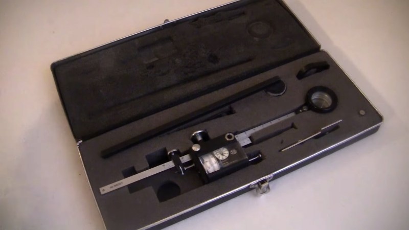
The polar planimeter being discussed is a higher end unit from the 1960’s. Interestingly, the first polar planimeters were invented in the early 19th century even before the math that describes their function was completed. A lever is placed in a fixed position on one end and into the planimeter on the other. The planimeter itself has another arm with a reticle on it. The unit is zero’d out with a button, and the outline of the shape in question is traced in a clockwise fashion with the reticle.
What makes the polar planimeter capable of measuring in multiple dimensions is the fixed arm. The fixed arm pivots around, allowing the planimeter to track angle changes which affects the output. So, the planimeter isn’t just measuring the length of the perimeter, but the size of the perimeter. The final measurement is output in square inches.
Overall it’s a really slick tool we didn’t know existed, and it’s fascinating to see how such problems were solved before everything could be done with a mouse click or two. Be sure to check out this 100+ year old reference set to round out your knowledge of past knowledge. Thanks to [Zane] for the great tip!


I’m a fan of these old calculation devices, this creator has quite the video collection. Recently invested time again in the slide rule, just because :)
Same. Binged the whole playlist. Bought an Addiator. Bought a Monroe L Series. Bought way too many slide rules.
I want to see someone take some cheap digital calipers and make a digital slide rule.
I’ve built one as a mechanics and manufacturing course exercise. We got to pick something small to make that involves laser cutting and bending sheet metal, so I made a planimeter. It used a short M6 screw with a washer that was ground thin at the edge as the rolling element. The screw was pinched at the ends between two ball bearings inside a flexible metal capsule. A nut on the screw moved a needle on a linear scale to count full revolutions, and a short cylinder with lines drawn on it read degrees. I think I made it read millimeters of travel, so it would result directly in square millimeters.
It wasn’t extremely accurate, but I got to within 5% by going around the figure clockwise, taking the reading, then going anti-clockwise and noting how much was left in the dial as it never got back to zero. The planimeter would roll less than it should because of friction, but the error was the same amount going both ways, so adding half the remainder to the measured number gave you a better estimate.
Good day. I am currently taking a mechanics course and I was assigned to build a polar planimeter too. But I can’t still understand what should be the measurements for constructing it. In my understanding the ration between two hands is very important to the final result.
Can you please give me a piece of advice on how to calculate the dimensions of the planimeter?
I need to construct it too)) How is it going?
The principle is very simple. The pivoting arm causes the roller to roll a different distance for the same motion of the pointer depending on the distance, so as long as you’re returning to the same point, the difference in measuring “Y” travel depends on how far away you went along “X”. If there was no difference, you return back to zero, and if there was a difference you get something left over.
The theory may look complicated and esoteric, but with this type of planimeter the area that you covered is simply the difference you counted multiplied by the arm length.
There’s another planimeter that works roughly in the same way, but utilizes a knife edge. You measure the arc distance from the starting point to the end and multiply that by the arm.
https://www.boatdesign.net/gallery/planimeter.1124/full?d=1493443229
Of course if you build one, make sure the blade tracks straight by adjusting the pin point at the end.
Planimeters were used historically e.g to measure ship/boat hull cross-sections out of plans to figure out the displacement.
If you have the drawing on paper, they can be useful to quickly measure a cross-section of a beam or a structure etc. If you know the neutral center of a cross-section (or can guess it), you can use the area of the cross-section with Steiner’s rule (parallel axis theorem) to estimate things like mass moment of inertia or how much the beam would resist twisting relative to some axis.
Apparently there are new mechanical and electronic planimeters available for purchase today:
* TAMAYA (Japan) Planix Digital Planimeters
https://tamaya-technics.com/en/planix/
https://www.tamaya-technics.com/e_site/planix567_e.html
* Planimeter Sliding Roller Drum Type Superior Quality in Box Size 28″/ 710 Mm $109.00
https://www.amazon.com/Planimeter-Sliding-Roller-Superior-Quality/dp/B09KCJ3BGT
This tool looks to be ideal for building with an optical mouse sensor to be really precise, and have a digital readout so no need to read vernier scales.
Would like to see someone make/hack an isometrograph from panagraph parts
Brings back memories…in college PChem we learned different ways to measure area under a curve. The prof showed us the planimeter but I never got to use it, as she kept it in her office and I did my work in the evenings. Instead I used the cut-and-weigh method for stripchart recorders. The paper was quite uniform, so you weighed a piece, say 20×20 squares, then cut out your curve and weighed it. The ratio told you the area of your curve. It required a good balance; the ones we used were single-pan analytical units, precise to 0.1 mg.