Polar Planimeter Quantifies Area By Plotting Perimeter

These days it’s hard to be carry the label “maker” or “hacker” without also being proficient in some kind of CAD- even if the C is for Cardboard. But before there was CAD there was Drafting and its associated arts, and one couldn’t just select a shape and see its area in the square unit of your choice. So how could an old school draftsman figure out the area of complex shapes? [Chris Staecker] introduces us to the polar planimeter, a measuring tool created specifically for the purpose and explained in full in the video below the break.

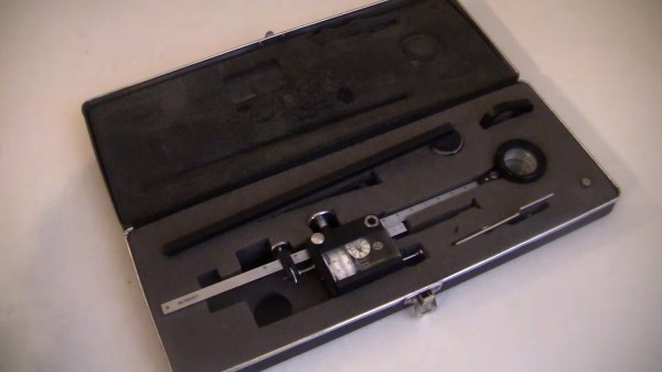
The polar planimeter being discussed is a higher end unit from the 1960’s. Interestingly, the first polar planimeters were invented in the early 19th century even before the math that describes their function was completed. A lever is placed in a fixed position on one end and into the planimeter on the other. The planimeter itself has another arm with a reticle on it. The unit is zero’d out with a button, and the outline of the shape in question is traced in a clockwise fashion with the reticle.

What makes the polar planimeter capable of measuring in multiple dimensions is the fixed arm. The fixed arm pivots around, allowing the planimeter to track angle changes which affects the output. So, the planimeter isn’t just measuring the length of the perimeter, but the size of the perimeter. The final measurement is output in square inches.

Overall it’s a really slick tool we didn’t know existed, and it’s fascinating to see how such problems were solved before everything could be done with a mouse click or two. Be sure to check out this 100+ year old reference set to round out your knowledge of past knowledge. Thanks to [Zane] for the great tip!

Continue reading “Polar Planimeter Quantifies Area By Plotting Perimeter”

Lewis Latimer Drafted The Future Of Electric Light

These days, we have LED light bulbs that will last a decade. But it wasn’t so long ago that incandescent lamps were all we had, and they burned out after several months. Thomas Edison’s early light bulbs used bamboo filaments that burned out very quickly. An inventor and draftsman named Lewis Latimer improved Edison’s filament by encasing it in cardboard, earning himself a patent the process.

Lewis had a hard early life, but he succeeded in spite of the odds and his lack of formal education. He was a respected draftsman who earned several patents and worked directly with Alexander Graham Bell and Thomas Edison. Although Lewis didn’t invent the light bulb, he definitely made it better and longer-lasting. Continue reading “Lewis Latimer Drafted The Future Of Electric Light”

FreeCAD TechDraw Workbench Tutorial

FreeCAD started out a little shaky, but it has gotten better and better. If you are trying to draw a schematic, it probably isn’t the best way to do it. However, it is a great graphical alternative to OpenSCAD for 3D printing and even incorporates OpenSCAD if you don’t want to choose. However, if you have a 3D part — regardless of how you want to create it in real life — having a proper mechanical drawing is very valuable. FreeCAD’s TechDraw workbench makes this very easy and [Joko] has a tutorial that shows exactly how to do it.

Machinists everywhere are used to looking at these drawings that typically show a top view, a front view, and a side view. The program will automatically project the views you select and then allows you to pick dimensions. It creates them and keeps them up to date if you change them in the model later.

Continue reading “FreeCAD TechDraw Workbench Tutorial”

Automate The Freight: Platooning

On yet another one of those long, pointless road trips that seemed to punctuate my life starting when I got my license, I was plying the roads somewhere in eastern Pennsylvania with a friend. He told me that on long trips he’d often relieve the boredom by finding another car from the same state as his destination, and then just follow it. I wasn’t sure then how staring at the same car, hour after hour, mile after mile, would do anything but increase the boredom while making you look sort of creepy, but it seemed to work for him.

What works for college kids in cars also works for long-haul truckers, and the concept of a convoy has long been a fact of life on the road and a part of popular culture. Hardly a trip on the US Interstate goes by without seeing a least two truckers traveling in close formation, partly for companionship and mutual support but also for economic reasons. And now technology is poised to take convoying to the next level, as platooning becomes yet another way to automate the freight.

Continue reading “Automate The Freight: Platooning”

How Precise Is That Part? Know Your GD&T

How does a design go from the computer screen to something you hold in your hand? Not being able to fully answer this question is a huge risk in manufacturing because . One of the important tools engineers use to ensure success is Geometric Dimensioning and Tolerancing (GD&T).

A good technical drawing is essential for communicating your mechanical part designs to a manufacturer. Drafting, as a professional discipline, is all about creating technical drawings that are as unambiguous as possible, and that means defining features explicitly. The most basic implementation of that concept is dimensioning, where you state the distance or angle between features. A proper technical drawing will also include tolerances for those dimensions, and I recently explained how to avoid the pitfall of stacking those tolerances.

Dimensions and tolerances alone, however, don’t tell the complete story. On their own, they don’t specify how closely the geometric form of the manufactured part needs to adhere to your perfect, nominal representation. That’s what we’re going to dig into today with GD&T.

Continue reading “How Precise Is That Part? Know Your GD&T”

Truly Terrible Dimensioned Drawings

I’m in the planning stages of a side project for Hackaday right now. It’s nothing too impressive, but this is a project that will involve a lot of electromechanical parts. This project is going to need a lot of panel mount 1/8″ jacks and sockets, vertical mount DIN 5 connectors, pots, switches, and other carefully crafted bits of metal. Mouser and Digikey are great for nearly every other type of electrical component, but when it comes to these sorts of electromechanical components, your best move is usually to look at AliExpress or DealExtreme, finding something close to what you need, and buying a few hundred. Is this the best move for a manufacturable product? No, but we’re only building a few hundred of these things.

I have been browsing my usual Internet haunts in the search for the right bits of stamped brass and injection molded plastic for this project, and have come to a remarkable conclusion. Engineers, apparently, have no idea how to dimension drawings. Drafting has been a core competency for engineers from the dawn of time until AutoCAD was invented, and now we’re finally reaping the reward: It’s now rare to find a usable dimensioned drawing on the Internet.

This post is going to be half rant, half explanation of what is wrong with a few of the dimensioned drawings I’ve found recently. Consider this an example of what not to do.  There is no reason for the state of engineering drawing to be this bad.

Continue reading “Truly Terrible Dimensioned Drawings”