I2C is a wonderful interface. With four wires and only two GPIOs, you can connect a whole lot of sensors and devices – in parallel, at that! You will see I2C used basically everywhere, in every phone, laptop, desktop, and any device with more than a few ICs inside of it – and most microcontrollers have I2C support baked into their hardware. As a result, there’s a myriad of interesting and useful devices you can use I2C with. Occasionally, maker-facing companies create plug-and-play interfaces for the I2C device breakouts they produce, with standardized pinouts and connectors.
Following a standard pinout is way better than inventing your own, and your experience with inconsistent pin header pinouts on generic I2C modules from China will surely reflect that. Wouldn’t it be wonderful if you could just plug a single I2C-carrying connector into an MPU9050, MLX90614 or HMC5883L breakout you bought for a few dollars, as opposed to the usual hurdle of looking at the module’s silkscreen, soldering pin headers onto it and carefully arranging female headers onto the correct pins?
As with any standard, when it comes to I2C-on-a-connector conventions, you would correctly guess that there’s more than one, and they all have their pros and cons. There aren’t quite fifteen, but there’s definitely six-and-a-half! They’re mostly inter-compatible, and making use of them means that you can access some pretty powerful peripherals easily. Let’s start with the two ecosystems that only have minor differences, and that you’ll encounter the most!
The JST-SH buddies
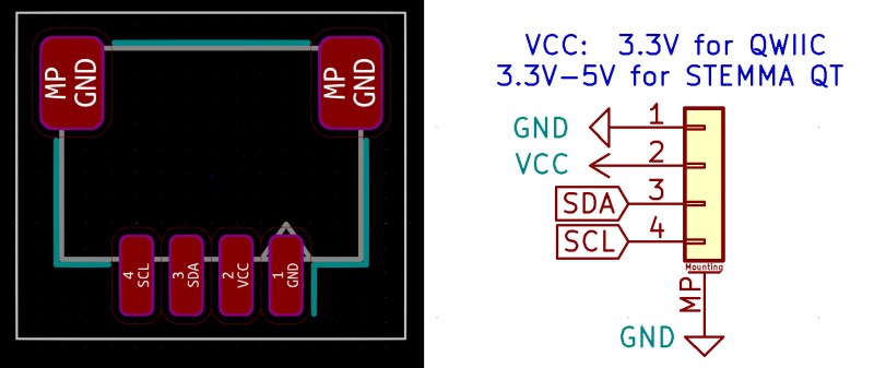
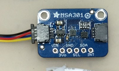
There’s two ecosystems of I2C modules that are based on four-pin JST-SH (1mm pitch) connectors, and they’re very interchangeable! One of them is Sparkfun’s QWIIC, and other is Adafruit’s STEMMA QT (pronounced ‘cutie’). Both of them are straightforward to add to your PCB, as long as you have a few JST-SH four-pin connectors ready. What’s more – Adafruit and Sparkfun connectors have the same pinout!
The connectors being used are JST-SH, surface-mount, with 1 mm pitch. Their JST family is SR/SH and the part number for the original JST part is SM04B-SRSS-TB, but you can find cheap third-party connectors with the same dimensions on LCSC using “1x4P SH 1mm” search terms. Both QWIIC and STEMMA have pages to refer to when doing your own designs. Now, what are the differences between the two?
QWIIC limits itself to 3.3 V on both host (i.e. MCU board, providing power) and device (i.e. sensor, consuming power) side – a reasonable decision, simplifying things a lot. An overwhelming majority of devices we work with nowadays are 3.3 V, to the point where level-shifting problems are mostly unheard of. Perhaps, the eventual move to 1.8 V will shake that up, but we are not there yet, and factors like LED forward voltages will necessitate some kind of higher-than-1.8 V reference in our project when we get there, anyway. So, 3.3 V power and two 3.3 V logic level I2C signals on a single connector – plain and simple. Chances are, you can already add QWIIC to your sensor or MCU board – without any additional components required but the connector itself!
In contrast, STEMMA QT is built to expand on the possible educational and convenience value, in line with other Adafruit offerings. As such, it allows for 5 V hosts – with devices designed to work in the 3.3 V-5 V power and logic level range, making sure that your Arduino Uno is not left out of the game. This is possible because every module has a low-dropout voltage regulator like the AP2112K or the MIC5219, which helps keep things almost-3.3 V when you feed the board with 3.3 V. The reasoning is simple – apart from 5 V hosts like Arduino Uno, you might also want to chain your STEMMA devices with some power hungry-devices, like I2C-savvy servos or RGB strips. In short, plugging anything into anything, with any kind of chain, shouldn’t result in magic smoke escaping – an event rarely on the TODO list of a maker’s project. One more upside of STEMMA QT is standardization of device board sizes, letting you easily mechanically integrate new sensors into the project before they even arrive to you, and spawning nifty hacks like this STEMMA Qt 3D-printable hotswap socket!
To sum up the voltage compatibility situation – all STEMMA QT devices will work with QWIIC hosts; and all QWIIC devices will work with 3.3 V STEMMA Qt hosts; as a result, any QWIIC host is also technically a STEMMA QT host. QWIIC devices will be fiercely incompatible with 5 V STEMMA QT hosts, but such hosts are rare, and you just have to be on the lookout when interfacing QWIIC devices with STEMMA hosts. Another minor hiccup with both of these standards is lack of interrupt signals – that, I will expand on below, in the “Breakout Garden” section. For now, let’s take a look at STEMMA QT’s bigger sister!
Chaining QWIIC And STEMMA modules
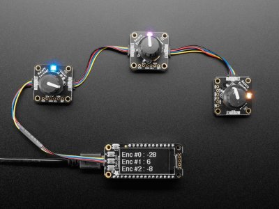
Oh, right, chaining! Both QWIIC and STEMMA QT are chaining-friendly – many modules offering a second JST-SH connector on the opposite side of the board, with the same signals passed through. This lets you wire up your projects in a comfortable way, not having to locate a spot in your project where you can put your MCU while not having it too far from all of your sensors, or not resorting to breadboards for splitting your I2C bus into multiple stubs. Many host boards also offer multiple sockets wired in parallel, and there’s “splitter” boards available that turn a single JST-SH cable with I2C into, say, three extra sockets.
As long as your addresses don’t conflict, you will generally be fine wiring an I2C bus for a project in such a way. Oh, and make sure to not overload your I2C bus with all the pullups added in parallel – they tend to be 10 kΩ for STEMMA QT and 2.2 kΩ for QWIIC, and at least in case of QWIIC, it seems you’re typically able to cut two trace jumpers with an xacto knife to disconnect the pullups on any module. With all non-Pico-based Raspberry Pi boards having 1.8 kΩ onboard pullups on their I2C ports, you might find yourself needing to do that quite early on as you chain devices.
The Bigger, Blacker Connector
STEMMA has the same pinout as STEMMA QT and QWIIC, but a different, larger connector. It, too, is flexible when it comes to voltages you can output on the host end, and in turn, must be able to accept on the device end. Most of the advantages in STEMMA QT section apply to STEMMA, save for QWIIC compatibility and reduced physical size.
STEMMA connectors are JST PH connectors with 2 mm pitch, with JST part number being S4B-PH-SM4-TB, and cheap third-party connectors available with “1x4P PH 2mm” search terms. They’re a bit easier to tackle with a soldering iron than the 1 mm pitch SH connectors, and for larger boards, they’re a good fit.
JST-PH is one of those cases where surface-mount sockets turn out to be way more resilient than the through-hole ones. With a tougher retention mechanism, your fingernails will no longer suffice – you’ll likely want to use your trusty pair of blue flush cutters for unplugging these! I2C-carrying STEMMA also has an GPIO and analog STEMMA counterpart, using 3-pin JST PH connectors for things like WS2812 strips – where 5 V compatibility becomes exceptionally handy. However, 4-pin connectors are firmly reserved for I2C, and such consistency is hard to not appreciate in educational and prototyping environments – checking the dozens of tutorials Adafruit has involving STEMMA devices, the “Wiring” sections in those are extra straightforward! On some STEMMA hosts, you will also be able to rewire the port to either 3.3 V or 5 V through a solder jumper.
Just Can’t Get Into The Grove
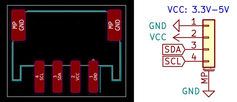
 The Grove connector standard, oldest of them all, is now somewhat of a black sheep among the I2C connector ecosystems, and is here half as a piece of history, half as a cautionary tale. Contrary to principles of open-source ecosystems, Grove uses a proprietary connector, which has makers scramble for its proper identification as they try to find a source that is not SeeedStudio. Unlike all the other standards listed here, when you see a 4-pin Grove connector, you don’t know if it’s for I2C, UART, two digital GPIOs or something analog, which ruins the whole “plug and play” idea.
To those of you unfortunate to have to interface with Grove, it also uses 3.3 V – 5 V range of possible voltages, but is less interested in explicitly advertising which one is used, or letting you change that – both things that STEMMA does without breaking a sweat. It uses the same pinout for I2C as QWIIC/STEMMA do. If you have a STEMMA-compatible (JST-PH) cable, you can sand it down a bit to make it fit into a Grove connector.
In other words, there’s a good reason you don’t see Grove connectors used more often. I couldn’t help but notice that Tom’s Hardware, when writing the conclusion section of their own I2C connector ecosystem overview article, failed to find an advantage of Grove that wasn’t generic to every other ecosystem they talked about. Unless you want to resign to paying SeeedStudio for every connector and cable you ever need, and are okay never being compatible with connector ecosystems worth investing effort into, I strongly recommend you avoid using Grove on your boards. Let’s spend time on the next – underappreciated – option instead.
A Stroll In The Breakout Garden
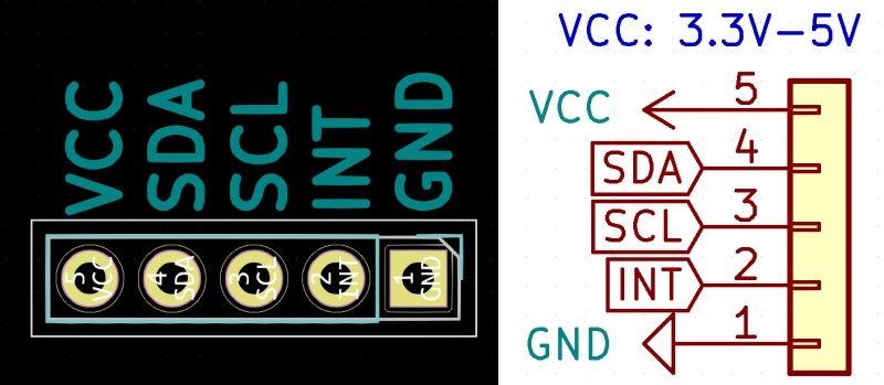
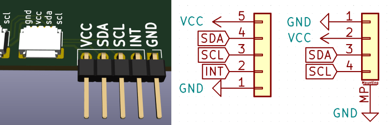
The Breakout Garden ecosystem by Pimoroni uses an elegant pinout – taking a row of five pins off the Raspberry Pi GPIO header, pins 1 to 9, including 3.3 V, SDA, SCL, a GPIO pin and, of course, GND – in this order. They sure don’t hold a patent to this pinout – a whole lot of hackers, myself included, have been using this pinout for ages on our I2C-equipped boards. Such a pinout, for a start, means that you can plug any Breakout Garden board onto a Raspberry Pi directly.
You’re not limited to that, either – Pimoroni also offers nice slide-in connectors that let you hotswap Breakout Garden modules. And, if you don’t want to use the slide-in sockets, just solder angled male pin headers and treat them like any other module. Breakout Garden modules typically have a 3.3 V – 5 V input voltage range. They also claim reverse polarity protection on every module, so, inevitably plugging a module backwards shouldn’t delay your project.
 With the Breakout Garden pinout, you also get an extra GPIO, which is most commonly either NC or used as an interrupt pin. Interrupt pins are under-appreciated when working with I2C devices – they let you offload your CPU and your I2C bus, avoiding polling and letting your I2C peripheral signal you when it wants your attention, something not possible through the I2C bus alone. For a few modules, like this haptic actuator driver, the GPIO is used as a “trigger” pin instead, for action synchronisation. That does hurt the concept of chaining somewhat, of course – to be fair, though, so does the bulky hotswap socket. Not that you can’t connect Breakout Garden boards in parallel – after all, INT pin is typically disable-able for I2C devices, which will absolutely come handy, given the the puzzling decision of wiring all the INT pins together on their 6-socket Raspberry Pi HAT.
Adding basic support for “Breakout Garden”-like connection in your project is as simple as adding a five-pin 2.54mm (0.1″) pin header – and with that, you instantly get Raspberry Pi GPIO header compatibility. When it comes to creating your own modules, I couldn’t find any dimensions or an official “how to create” modules, so you’re probably not meant to do that – which doesn’t mean that you can’t reverse-engineer the schematics and the dimensions and then try anyway, but it sure is quite discouraging. If you want to add a Breakout Garden socket, they have two rows of pins that are exactly 5.08mm (0.2″) apart, and provide convenient plug & play connectivity, though with the cost of £1 per socket (not including shipping), the slide-in sockets are the most expensive to use of these all.
Conveniently Crimped Cables
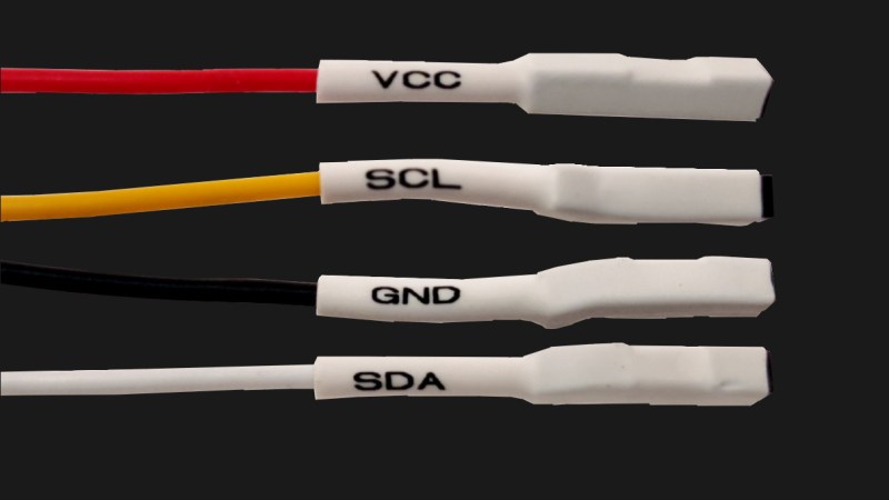
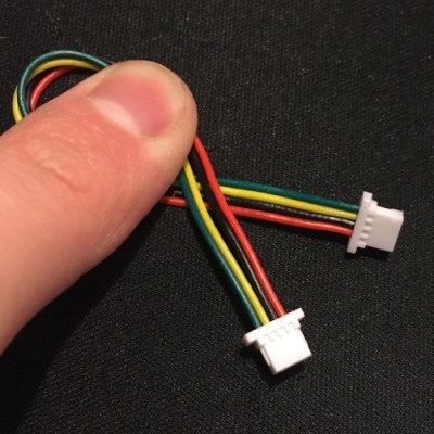 In the market for some JST-SH accessories? You really can’t go wrong with the SMD connectors; however, you absolutely can go wrong when it comes to pre-crimped cables. Crimping JST-SH with its 1 mm pitch is far from easy, and buying your own cables is your best bet – except for when they come miswired. A year ago, I was preparing for a project and bought a bundle of JST-SH cables, pictured to the right. Upon closer inspection, something felt off.
Turned out that they had their cable ends wired in the opposite direction, one’s pinout reverse to that of the other – with likely disastrous consequences when used as an interconnect. The cables I bought will require some careful rewiring with tweezers, and next time you are shopping for third-party JST-SH cables so that you can wire up your next project, you will know to inspect the pictures before pressing the “Buy Now” button.
Mentions Of Variable Honorableness
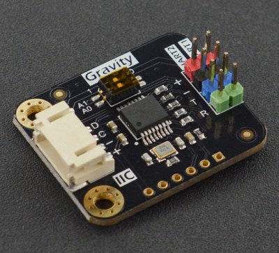 If you’ve ever worked with DFRobot parts, you might’ve seen JST-PH 4-pin (or 3-pin) connectors on their boards, too – they’re from their ecosystem called Gravity. Puzzlingly enough, Adafruit claims that STEMMA is compatible with Gravity, apart from their non-I2C devices – since Gravity does the same thing that Grove does, where a 4-pin connector doesn’t guarantee I2C. However, checking the pinout for Gravity I2C devices, it seems that every single pin is in a different spot, in particular, ground and power being reversed. Just like STEMMA, they use 3-pin connectors for digital and analog devices. The fun part is, they also managed to change the pinout for those at some point, also reversing the power pin polarity – while still using the same connector, a no-no for connector standards. Proceed with caution!
EasyC is basically QWIIC copied to a T, with the same pinout, connectors, chaining abilities and 3.3 V voltage limit – but not mentioning QWIIC in any way in their webpages and resources, which is a disappointment. Interoperability of different ecosystems is part of what makes them valuable, and arguably, you could be more inclined to buy from them if you knew that the standard they’re using is a widely accepted one – as opposed to “random pinout on some connector”. EasyC is driven by a Croatia-based e-radionica company, producing a medium-sized assortment of useful modules, including quite a few Chinese module clones and remixes – at European prices. Design files for their modules are not linked to from product files, but at least some of them seem to be on their GitHub! Interestingly enough, they also stock a 5cm “EasyC” cable which, upon closer inspection, has the same reversed wiring as the cables I told about in the previous section. Perhaps, putting a bit more thought into the EasyC ecosystem would be warranted.
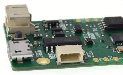 Sometimes we see companies making an attempt at a JST-SH thing, but not quite getting there. An example of that is a somewhat recent board by Lolin, the Lolin D1 Mini Pro, with a JST-SH 4-pin connector on it labelled “I2C”. You could be forgiven for thinking that this is a QWIIC-like pinout; given that this connector is marked “I2C”, one could argue they’ve been tricked, backstabbed and quite possibly, bamboozled. Instead of GND-VCC-SDA-SCL pinout, this board is using GND-SDA-SCL-VCC, and it appears there’s even a few accessories like shields made with this pinout in mind. It’s as if someone sent Lolin a letter saying “hey, you should put I2C on a JST-SH connector” and then refused to elaborate further. Thankfully, with the GND pins matching, the likelihood of destroying things is not as extreme.
Building Your Own Things? Need Guidance?
Which one of the standards should you follow when designing your own boards? I have provided you with all the information you could ever need to make your own decisions, but if you’re looking for a recommendation or a guideline, I will happily provide one, too.
I personally don’t use full-sized STEMMA (JST-PH) connectors, as way too often, they’re bulky enough to make the PCB itself seem small, and can make small boards a bit unwieldy due to their height – plus, they can be harder to unplug. The JST-SH connectors, however, are way too enticing due to the prospect of being compatible with two ecosystems at once, as long as I avoid 5V hosts. And – a simple, standard pinout 5-pin header provides a surprising amount of benefits for how quickly you can add it!
In short, I recommend that you combine a Breakout Garden-like pin header and the QWIIC/STEMMA QT JST-SH connector on your boards. This way, you will always have compatibility with three out of the four ecosystems worth talking about, and connecting your I2C board to a Raspberry Pi will be as straightforward as getting five jumper cables. With this combination, you will never have to think about I2C header pinouts ever again, and you’ll have an interrupt signal handy for the times when you really could use one.
Do you have to add level shifting? Not if you don’t use 5 V in your projects, and especially not if you’re making a breakout for an IC that has a wide range of input voltages, like, say, I2C EEPROMs and RTCs. I personally work with mainly 3.3 V, and I don’t have reels of AP2112 regulators to sprinkle on every board I make – thankfully, I don’t have 5V I2C hosts, either. In case you do want to make your devices 5 V-compatible, you can’t go wrong with the classic, incredibly elegant, and inexpensive MOSFET solution for I2C level shifting!
Conclusion
Out of these, QWIIC, STEMMA and Breakout Garden have so far stood the test of time, with hobbyist electronics companies backing them all the way there. It is only fair that we benefit from the standards they created. Hopefully, the insights and the instructions provided get us closer to universal interoperability days, when one hacker’s MCU board can seamlessly interface with other hacker’s sensors. From there, one day, our favourite SSD1306 OLED breakouts might start arriving into our mailboxes equipped with a JST-SH connector and an extra cable. Today is not that day, but with every JST-SH footprint we add to our PCB, I believe we will see to it soon.


Olimex has their UEXT connector standard.
10 pin IDC with 3V3 power, I2C, UART and SPI.
https://en.wikipedia.org/wiki/UEXT
Thant’s the great thing about standards, there’s so many to chose from!
I’ve been using the QWIIC/STEMMA pinout on my boards for a while, didn’t even know that my pinout matched these. I mostly use JST-XH connectors though.
About level shifting, as long you only have pull-ups to 3.3V, you shouldn’t need any level shifting. Every 5V host/device will work with 3.3V level signals.
Check your datasheet. Plenty of 3.3v devices can’t tolerate 5v signals, and if you’re trying to send 5v signals to a device rated for 4v maximum you can’t expect the manufacturer to support your application.
Not really. No I2C device will drive the lines high, so the signal will always stay between 0 and 3.3V. The only question is whether the 3.3V will be high enough for the 5V device. In most cases it will work, but for anything serious you need to check Vih in the datasheet.
The leakage current through the 5V device may also be higher if the high level is not high enough.
“The only question is whether the 3.3V will be high enough for the 5V device. In most cases it will work”
I wouldn’t say “most cases” – Vih pretty frequently (I’d almost say usually?) tends to be 0.7-0.8*Vcc which is technically outside of 3.3V. The other issue, though, is that unless the Vih is pretty low on the 5V device, the timing can change pretty dramatically if the bus is loaded (relative to the pullup strength).
The other issue you can run into, of course, is when one side’s powered and the other isn’t, which can flat-out damage or destroy stuff (BeagleBone Blacks are *incredibly* sensitive to this) since you’re back-powering the unpowered device likely through its protection diodes. And while you might not *think* milliamps of current can do things, oh, let me tell you some stories.
You can do it properly with a single FET and two resistors. It’s not worth the time it takes to think about it.
The best case is when the 5V device has an input with thresholds similar to HCT or ACT CMOS logic, where Vih is only about 40% of Vdd (2V if you’re powering the CMOS at 5V).
Drop some voltage with a diode or 2?
I don’t think that I2C addressing is wonderful. After reading about it, it appears that they wanted to sell off the 128 addresses to the highest bidder.
Also there are issues with putting two of the same devices on the same chain.
I want a different standard.
There are already are many different communication standards: SPI (and even here multiple variants), I2C, UART, 1 Wire, CAN, etc. Each has their own strengths and weaknesses, the application requirements are what determine which comm is best suited to the task. Whether or not you think I2C is wonderful is subjective, entirely depending on your needs and doesn’t necessarily reflect on the standard itself.
I’ve been dealing with this in a current project of instrumenting my mountain bike so I can measure suspension damping/compression rebound changes: I want to have 4-6 accelerometers on the bike, all hooked to one central data gathering micro. Some accelerometer chips allow you two addresses via a hardware change. At least I2C flash chips allow you 8 addresses via hardware jumpers. Thankfully, the particular chips I use are also capable of SPI so I can run as many chips as I have digital pins available, but at the cost of six wires. So I’m using phone line/jacks as my wiring solution for distant chips, and CS pins for my addressing woes.
For cases like this where I2C is your only choice and you need multiple chips with the same address that you cant change they make I2C expanders that effectively reallocate each port to a different address. Kind of a kludgy bodge but works in a pinch.
I2C multiplexing is most certainly not a hack because the protocol was specifically designed to support it.
TCA9548A (i2c multiplexer) is a smart little device for harsh environments. Allows different supply voltages/bus levels and an unruly device can be isolated from the bus.
Usage is transparent and easy.
I highly recommend it.
Mouser says it will be available at 16/01/2023. LCSC has them on stock for only $ 4 USD per item. Agonal respiration in 3…2…1.
LOL who would’ve thought there’d come a time you’d need a laryngoscope and a #10 ETT handy to browse essentially a hobby *component* supplier?
I haven’t tried it yet, but there’s a clever bodge in a StackOverflow answer about how to use multiple I2C devices with the same address: https://electronics.stackexchange.com/questions/5096/how-to-resolve-i2c-address-clashes/392155#392155
ooh this is niiice, this is basically chip selects for I2C devices! dope!
ATMega328 provides about 40 mA per pin, ESP32 20 mA per pin.
BME280 (Temp, Press, Hum) draws less than 6 µA, LSM303AH or MMA8451Q (3d accel) draws less than 170 µA.
So the hassle with resistor and Schottky can sometimes be replaced by directly power those from the µC. Side benefit: easy device reset.
I’v always recoiled from the Grove connector thing. All I want is pins on 0.1 inch centers and I can use readily available stuff to connect it up. Heck, just give me pads on 0.1 centers on the PCB that I can either solder wires to or add a header of my own if I really want to. Now we are talking! But some darn proprietary connector. No thanks.
If the pins are on 0.1 centers, you can always desolder it and go from there, but I just avoid it.
“next time you are shopping for third-party JST-SH cables so that you can wire up your next project, you will know to inspect the pictures before pressing the “Buy Now” button”
Don’t trust a suppliers pictures. Unfortunately shopping for cables is just a total crapshoot in my experience. What you end up buying might be high quality and match the pictures. It might also be total crap with some pins coming out of the connector from factory, bad cables, and random wiring direction. You’ll have to inspect each batch of cables as they come in. And sometimes you’ll have to inspect every cable (though I’d suggest just chucking the lot if it comes to that point. Nobody likes the frustration that comes from having to figure out if it’s the cable or something else in your project causing you grief. Especially if it’s intermittent faults).
I dunno about you but in my experience, if you shop for cables at mouser or digikey or sparkfun or adafruit, you will always get good stuff. Is it really worth it to pinch pennies on your project? All those hours of hard work, pay more and use quality stuff.
If your pin header has a square pad on it, please, PLEASE make it the GND pin.
The normal convention is that the square pin is pin 1. I don’t see any reason why it should have to be ground…
IPC-7351 says pin 1 is cathode
The China slur was, IMHO unnecessary.
Interesting article, nevertheless.
I missed the China thing, what was it? “Bigger Blacker” made me wonder how it got past the sensitivity editor though.
“[Y]our experience with inconsistent pin header pinouts on generic I2C modules from China will surely reflect that.”
As if only China made them. I made a couple myself!
Oh, same, I have designed a whole slew of I2C stuff that I nowadays wish I put a JST connector on! But I’m specifically talking about the breakouts we buy somewhere else, for me, it’s always been Chinese retailers. I have a lot of love for what they offer to people on a budget, which doesn’t negate that, talking about specifically I2C interconnects, the experience is not where it could be.
For a lot my projects that need external connections (e.g. a sensor a few feet away, not internal to the device or daughter board) I just started using USB-C ports and cables .. you can fit a lot of GPIO onto those and they’re so much cleaner to deal with. Overkill for just I2C, but it’s a lot nicer to deal with
You do need to be on the lookout with regards to which cables connect which pins, however – and the rotation, too!
ive always just rolled my own. because i don’t like product ecosystems. especially when they require expensive or hard to crimp connectors.
I’m putting sensors in every room and it sure is nice to be able to use all off the shelf parts with no soldering. Makes for easy maintenance and documentation. Also when we sell the house it’s better if it all looks professional.
I like the Electric Dollar Store stuff for prototyping. The board to board connectors are plain headers, but the modules also include castellated pins that make it easy to connect a few together. This is developed by the same guy as the I2CDriver and SPIDriver devices
https://electricdollarstore.com/
ooh wonderful, and the plain header pinout is the same as QWIIC! yaay!
Does anyone have a good Arduino tutorial that explains how to encapsulate I2C data on an Arduino so it’s not just spamming all the time. Basically showing how to take a bunch of non I2C sensors maybe something complicated like a non-I2C GPS module for example. That has a lot of settings and streaming data functions. Which is connected to an Arduino. Then laying out settings and values for the device which you can then request or store the values being sent or received on demand. Most tutorial I’ve found expel all their energy on explaining the I2C bus protocol or how to talk to existing I2C stuff but not how to make your own customized I2C device. I found one tutorial that sorta does this but maybe the person lost interest or was time constraint. It sorta leaves you hanging.
If you need to add 5V compatibility to a 3V board, easiest/cheapest is going to be the original level translator circuit from AN10441. Just two logic-level gate FETs and the pull up resistors on either side. Nice thing is that it works even if you have the same voltage on each side and is only a few cents.
A little bit offtopic, but can anyone recommend a device to create those nice labeled heat-shrinkable tubings?
Thx
I use the Brother PT-D600 with a no-name shrink tube cartridge from Amazon with great results. If you go with a different label maker, just make sure it’s compatible with shrink tubes.
Golly! This consumable stuff is insane expensive… Amazon wants 24 € to 28 € for 4,5 meter of shrink tubing…
I second the reccomendation for brother. But definitely don’t spend the asking price for the tubing. Go to Amazon. The knockoff stuff is just as good as the OEM.
The printer wastes (intentionally?) a ton of material on either side of the print, so you’ll definitely want to steer clear of the super expensive stuff.
The printer wastes a bunch of material because of how the cutter works. If you want a batch of labeled tubes, the way to do it is to combine a few together as one long print and cut them up with scissors when you’re done. That’s a pain when you’re printing tape because the cut pieces are hard to peel, but you don’t have that problem with the tubing.
TLDR I am coming up with a port standard meant to be more uselful + Shameless Plug as example:)
Qwiic and Stemma QT are brilliant, user friendly connectors. That’s why I have gone with it on our first module. They are ideal for maker boards and modules but there are shortcomings when the use case demands a bit more. The above post is quite informative and some issues really hit home.
I’ve to confess that we are coming up with a new standard…
So brace yourself for our upcoming AMICA Link v1 Standard for I2C/Data and power that would be compatible with our upcoming SBC’s and hopefully boards from other companies.
The design philosophy / requirement for AMICA Link is:
+ Carry power (5v tolerance / 3.3v / Any V – negotiable)
+ Carry data (I2C default (optionally switchable to UART/CAN/RS485/USB))
Uses: IMU / Sensor / Power reporting / Switch solar panels and Bat sources
+ 1 GPIO (Multi use / Switching / Interrupts / 1 wire)
+ Protection / Detection (Voltage / Reverse – Shorts)
+ Low EMI / Shielding
+ Mechanical Strength – Plug / unplug a 1000 times
+ Ability to run longer lengths than usual (30cm – 30m)
+ Low cost connectors and cables
The connectors and cables can’t be more expensive than boards!
+ Make use of economies of scale
JST Cables are simple but shielded USB cables are dime a dozen
+ User friendly / reliability / end product friendly
A single cable is more protected, reliable and aesthetic vs JST wires protruding out of a end product.
+ High reliability mechanical enhancement options
For example armored cable sleeve, plug and then screw in place for robotics / high temp / high vibration env.
As a result we chose the USB Micro AB Receptacle and USB Micro A Plug along with shielded 5 wire cables as well as the option for both twisted and untwisted wires inside depending on use case. Another benefit is that a Micro A Plug wont fit into majority of devices such as a smartphone, yet a micro B Plug would fit into a micro AB and be able to to provide power.
The following proto module has both the Qwiic port and also the AMICA Link v0 Port.
https://twitter.com/VulcanIgnis/status/1521882473764122624
https://twitter.com/AMICABoard/status/1521885903823593474
Production SBC’s and Modules would feature the AMICA Link v1 standard which will include protection circuitry and follow the complete philosophy as closely as possible… v0 pin out is a personal use one with I2C and 3.3v power (reverse polarity of USB)
The power positions of AMICA Link v1 would be same as that of USB, D+ D- would be used for data (default SCL & SDA), the remaining pin for the GPIO line.
I’m a great Hackaday fan and much of my inspiration comes from Hackaday. Dear Hackaday hackers & readers if you have inspirations, ideas or requirements for AMICA Link v1, please feel free to ping me as v1 is not yet finalized.
EOF
Between Grove, QWIIC and STEMMA I prefer Grove. Grove connectors are way less expensive. LCSC parts sells thru hole and SMT for dirt cheap. Mouser sells the cable sets and connectors for a very inexpensive. Grove is a much better deal and they are not big or bulky connectors. Check out how I use them with the low cost China boards from amazon.
https://www.youtube.com/watch?v=W5we-2irERI&t=6s. Price check the STEMME, QWIIC and compare to Grove cost. The availability of Grove boards and functionality kicks but on everything else. PMOD can’t even come close.
I think PH and Grove are the right sized connectors for those of us who make our own boards. I prefer Grove for a few reasons: the cables have a colour code, I can buy them easily in a variety of lengths, its easier to swap wires on a Grove connector than it is on a PH, and they have an optional latch. As of May 4, 2022, I can buy just about any Grove wiring part from Digikey, but there are almost no PH parts available. Maybe PH is more popular so sold out? I’ve been having to order PH from Aliexpress.
What? NO mention of Clock Stretching? I’ve got some I2C sensors that require this (very annoying & hard to find) feature.
Bottom line, the sensor can pause the bus in the middle of transmission so it can catch up. Requires HW on the bus controller side to support. A lot of chips don’t support this.
Clock stretching is the worst. Except for multi-mastering I2C setups.
A friend of mine had this idea to create havoc and mayhem: “wouldn’t it be fun to create some rogue code on a microcontroller that would just crowbar the I2C clock line? You’d bring the system to its knees! Muhahaha!” He was shocked when I told him about clock stretching. All the good ideas are taken!
OK, but seriously. Both of these ideas create contention on the lines, with the expectation that all compliant devices will respect it. The problem is that the features are used rarely enough that many chips don’t. It sounds like a good idea, but man, in practice…
The coolest tip I ever heard was to put different resistors on different chips. Then you can use the analog voltage to tell which one is pulling the line down. I’ve never had to use this in anger, but it is super clever.
More I2C debugging tips: https://hackaday.com/2016/07/19/what-could-go-wrong-i2c-edition/
What?!?! No mention of the SAO bus? How many times has it graced these pages? Badges, anyone?
I’ve spent considerable time mulling this over and I haven’t found anything that makes me happy. The problem with most everything listed here is: too small. too fragile. mostly requires pre-made cables and PCBs. IMO not very hacker friendly. It should be something anybody can use with a breadboard or perfboard. And it shouldn’t die after a couple of replugs.
That “breakout garden” pin out looks interesting. But to be maximally useful that extra pin needs to be unique per device on the _bus_. This precludes daisy chaining and requires a star type topology. Still a tantalizing thought.
Haha! I guess the SAO _is_ kinda an I2C standard. Although honestly, most of the time the only wires that are active are VCC and GND.
What we need is an SAO I2C protocol to go along with the physical standard to encourage its use. More standards! :)
Would it not be better? In a single word: No.
We typically can get a board to product within 2 revs and always use the same pinouts across the same product line. It makes the documentation simple and lab/manufacturing folks happy.
We had to work with a sister division in different time zone on a product line for some management exercise. (They were thinking of offshoring.) They had 4 different prototype revision PCB for the *same* SKU but used 4 different JTAG pinouts for no reasons.
It was… A great article.
I mean, I still don’t know why I read it, but it was well written and now I fell I should add this page to a bookmark !
Clear, plenty of examples, enough pictures. Thank you !
am i stupid or is adding another ground next to vcc in the breakout garden pinoit also including the other 4pin pinout so you can have both at the same time
Nono, that’s correct! The 4-pin pinout is valuable specifically on a SH-type connector, though, having it on a pin header doesn’t help as much. That said, extra ground pins are always cool to have!
I2C was meant to connect on a single PCB. Anyway, the specification says:
If the length of the bus lines on a PCB or ribbon cable exceeds 10 cm and includes the
VDD and VSS lines, the wiring pattern should be:
SDA _______________________
VDD ________________________
VSS ________________________
SCL _______________________
If only the VSS line is included, the wiring pattern should be:
SDA _______________________
VSS ________________________
SCL _______________________
See UM10204, e.g. https://www.nxp.com/docs/en/user-guide/UM10204.pdf
So why having other pinout if the specification says something?
breakout makers don’t bother with the in-spec pinout, so it doesn’t make sense for hackers to bother with it, either
I think the STEMMA schematic is flipped. STEMMA is the opposite of STEMMA QT. Pin 1 is GND in STEMMA QT, pin1 is SCL for STEMMA. See https://learn.adafruit.com/adafruit-stemma-soil-sensor-i2c-capacitive-moisture-sensor/pinouts and https://learn.adafruit.com/introducing-adafruit-stemma-qt/technical-specs.