Four jumper wires with white heatshrink on them, labelled VCC, SCL, SDA and GND

The Connector Zoo: I2C Ecosystems

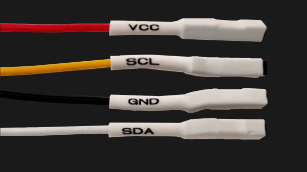
I2C is a wonderful interface. With four wires and only two GPIOs, you can connect a whole lot of sensors and devices – in parallel, at that! You will see I2C used basically everywhere, in every phone, laptop, desktop, and any device with more than a few ICs inside of it – and most microcontrollers have I2C support baked into their hardware. As a result, there’s a myriad of interesting and useful devices you can use I2C with. Occasionally, maker-facing companies create plug-and-play interfaces for the I2C device breakouts they produce, with standardized pinouts and connectors.

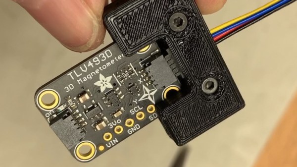
Following a standard pinout is way better than inventing your own, and your experience with inconsistent pin header pinouts on generic I2C modules from China will surely reflect that. Wouldn’t it be wonderful if you could just plug a single I2C-carrying connector into an MPU9050, MLX90614 or HMC5883L breakout you bought for a few dollars, as opposed to the usual hurdle of looking at the module’s silkscreen, soldering pin headers onto it and carefully arranging female headers onto the correct pins?

As with any standard, when it comes to I2C-on-a-connector conventions, you would correctly guess that there’s more than one, and they all have their pros and cons. There aren’t quite fifteen, but there’s definitely six-and-a-half! They’re mostly inter-compatible, and making use of them means that you can access some pretty powerful peripherals easily. Let’s start with the two ecosystems that only have minor differences, and that you’ll encounter the most! Continue reading “The Connector Zoo: I2C Ecosystems”

Quick-Swap Socket For Stemma QT Experiments

[kmatch98] shares a quick hack with us over at Hackaday.io – a 3D-printed socket for Adafruit Stemma QT-based I2C modules. Since Adafruit has standardized the dimensions for their Stemma QT boards, it’s possible to make a socket that would fit many different sensors at once, where the board just slides in.

This reminds us of sci-fi datadisks, or, thinking of something more grounded in reality, game console cartridges – except that here, the fun you’re having is from exploring all the different devices you can get to speak I2C. To make such a socket, you only need to 3D-print two plastic parts, put a JST-SH plug between them, and screw them together – if you want to modify these to your liking, .f3d sources are available. Now you no longer have to use fingernails or tin snips to take the JST-SH plug out of your modules!

[kmatch98] is no stranger to sharing his projects on Hackaday.io with us, and we’ve covered some of his larger projects before, like this CircuitPython-powered cyber-duck cyberdeck, or the 3D-printable Maypole braider machine!

Crimping Tools And The Cost Of Being Cheap

Crimp connectors provide an easy and convenient way to connect electronics while still allowing for them to be removed and swapped without having to reach for a soldering iron and desoldering wick. While browsing one’s favorite cheap shopping site, you may get the impression that all one has to do to join the world of crimp-awesome is order a $20 crimp tool and some assorted ‘JST’ and ‘DuPont’ (a Mini-PV clone) connectors to go with it. After all, it’s just a bit of metal that’s squeezed around some stripped wire. How complicated could this be?

The harsh truth is that, as ridiculous as the price tag on official JST and Mini-PV crimping tools may seem at hundreds of dollars each, they offer precise, repeatable crimps and reliable long-term stability. The same is true for genuine JST, Mini-PV and Molex connectors. The price tag for ‘saving a buck’ may end up being a lot higher than the money originally saved.

Continue reading “Crimping Tools And The Cost Of Being Cheap”

Bright White Night Light Fights E-Waste

E-waste is a gigantic problem, and it can seem impossible as a lone individual to make any kind of dent in it. But [akshar1101] is trying to do their part by looking past the defective aspects of broken, discarded electronics to draw out the possibilities of what’s left.

This friendly night light is made from the PCBs of four broken Nokia 5110 LCD modules. The screens were all toast, but the nice white LEDs that used to light them from the sides work just fine. [akshar1101] cleverly tied all the LED and GND lines together with single right-angle header pins. To power the LEDs, they wired up a JST receptacle to one of the PCBs and connected a 3.7 V lithium battery pack that sits underneath. [akshar1101] diffused the piercing white lights into a soft glow with two pieces of acrylic.

We love to see electronic components get saved from landfills, especially when they can be turned into something useful and beautiful. Something about the traces on these boards makes them visually interesting to us — it’s that little hiccup that interrupts otherwise parallel lines.

If all of your 5110 LCDs are in working order, you could spice one of them up with an RGB backlight.

Cheap Strain Relief By Casting Hot Glue In A 3D Print

[Daniel Roibert] found a way to add cheap strain relief to JST-XH connectors, better known to hobby aircraft folks as the charging and balance connectors on lithium-polymer battery packs. His solution is to cast them in hot glue, with the help of 3D printed molds. His project provides molds fitted for connectors with anywhere from two to eight conductors, so just pick the appropriate one and get printing. [Daniel] says to print the mold pieces in PETG, so that they can hold up to the temperature of melted glue.

The 3D models aren’t particularly intuitive to look at, but an instructional video makes everything clear. First coat the inside surfaces of the mold with a release agent (something like silicone oil should do the trick) and then a small amount of hot glue goes in the bottom. Next the connector is laid down on top of the glue, more glue is applied, and the top of the mold is pressed in. The small hole in the top isn’t for filling with glue, it’s to let excess escape as the mold is closed. After things cool completely, just pop apart the mold (little cutouts for a screwdriver tip make this easy) and trim any excess. That’s all there is to it.

One last thing: among the downloads you may notice one additional model. That one is provided in split parts, so that one can make a mold of an arbitrary width just by stretching the middle parts as needed, then merging them together. After all, sometimes the STL file is just not quite right and if sharing CAD files is not an option for whatever reason, providing STLs that can be more easily tweaked is a welcome courtesy. You can watch a short video showing how the whole thing works, below.

Continue reading “Cheap Strain Relief By Casting Hot Glue In A 3D Print”

The (Unnecessary?) Art Of Connector Crimping

The “Completion Backwards Principle” is a method of reasoning through a problem by visualizing the end result and then working your way backwards from that point. The blog post that [Alan Hawse] has recently written about the intricacies of crimping wires for plug connectors is a perfect example of this principle. The end result of his work is the realization that you probably shouldn’t bother crimping your own connectors, but watching him work backwards from that point is still fascinating. It’s also the name of a rock album from the 80’s by The Tubes, but this is not a useful piece of information in regards to electrical wiring.

Of course, sometimes people do silly things. Even though there are pre-crimped wires available online for a pittance, you might still want to do your own. With this in mind, [Alan] has put together an exceptionally detailed and well-research post that gives you all the information you could possibly want to know about crimping what is often erroneously referred to as the “JST connector”.

He starts by showing off some common examples of this connector, which if you’ve ever opened a piece of consumer electronics will be like looking through a High School yearbook. You might not know their names without reading them, but you definitely remember what they look like.

We’re then treated to an array of macro shots showing the scale of the pieces involved. If getting up close and personal with metal bits that are only a few millimeters long is your kind of thing, then you’re really going to love this part.

Finally, the post is wrapped up with a few words about the kind of crimping tools that are available on the market, and then a demonstration of his personal crimping method. While some tools would have you crimp both sets of “wings” at the same time, [Alan] tells us he finds taking them on individually leads to better results in his experience.

If this this little taste has left you hungry for a true feast of hyper-specialized knowledge, be sure to check out the Superconference talk by [Bradley Gawthrop].

Continue reading “The (Unnecessary?) Art Of Connector Crimping”

JST Is Not A Connector

When reading about cool projects and products, it’s common to see wiring plugs labelled “JST connector.” This looks fine until we start getting hands-on and begin hacking things together. Inevitably we find the JST connector from one part fails to fit in the JST connector of another. This is the moment we learn “JST” is not a connector specification. It is short for Japan Solderless Terminals Manufacturing Company, Ltd. A company whose history goes back to 1957 and their website (styled in 1999) lists hundreds of different types.

We can simplify to “JST connector” when chit-chatting about projects. But when it comes to actual hardware specification, that’s not good enough. Which JST connector?

Continue reading “JST Is Not A Connector”