Measuring voltages is fairly straightforward most of the time. Simply grab any old cheap multimeter, hook up the probes, and read off the answer. If, however, you need to measure very tiny voltages, the problem gets more complex. [Jaromir-Sukuba] designed a nanovoltmeter specifically to deal with this difficult case.
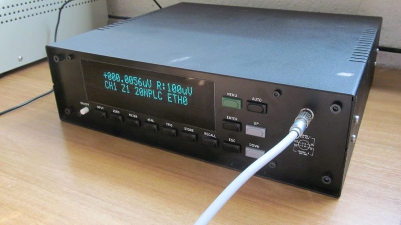
The nanovoltmeter is exactly what it sounds like: a voltmeter that is sensitive and stable enough to measure and report voltages on the scale of nanovolts. Having a tool that can do this reliably can be very useful when it comes to measuring very small resistances or working with ever-so-slight differential voltages.
The design of such an instrument is quite involved in order to reduce sources of noise and instability. The analog-to-digital converters must be of high quality, and they must be powered with their own supply to avoid excess noise. There are low-noise amplifiers and all manner of specialised subsystems required to handle the task. There’s even a 3D-printed cover to prevent airflow over a voltage reference in order to reduce noise from thermal variance.
Nonetheless, [Jaromir-Sukuba] does a great job of exploring what’s required to build a nanovoltmeter, and explains it well for an audience new to the field of such precise measurements. The resulting instrument was also capable of measurements with less than 25 nanovolts of noise peak-to-peak. It’s a great feat and those wishing to learn about how it’s done have an excellent resource to learn how.
We’ve seen other tricky measurement devices before, too. Did you know you probably already have a usable nano-ammeter? Now you do!
[Thanks to David Gustafik for the tip!]


That GitHub page was a fantastic read! Highly recommended.
The nano-world is handy for solving difficult problems.
https://youtu.be/77tymvTJDxo
It is interesting that to improve signal-to-noise ratio (SNR) [Jaromir-Sukuba] decided to use a low-noise-amplifier (LNA) in the meter’s input path made up of many massively-parallel Microchip MCP6V51 autozero/chopper op-amps.[1][2] To understand how this works see this app note from ADI: Paralleling Amplifiers Improves Signal-to-Noise Performance.[3]
Excerpting from the ADI app note:
The benefits of adding amplifiers in parallel are improved SNR and lower voltage noise density. For N amplifiers in parallel, the amplifier noise power is reduced by N and the input referred voltage noise density is reduced by Sqrt(N}. Put another way, each time the number of amplifiers is doubled, the amplifier noise power decreases by 2 and the amplifier’s input referred voltage noise density decreases by Sqrt(2). Note that paralleling amplifiers can only reduce the uncorrelated noise added by the amplifiers; it cannot reduce the noise due to other external noise sources (ex. resistors, sensors, other signal conditioning components, etc.)
* References:
1. NVM design, part 3 – selected details of circuit operation
https://github.com/jaromir-sukuba/nvm#nvm-design-part-3—selected-details-of-circuit-operation
2. Microchip MCP6V51 45V, 2 MHz Zero-Drift Op Amp w/ EMI Filtering
https://www.microchip.com/en-us/product/MCP6V51
3. Paralleling Amplifiers Improves Signal-to-Noise Performance.
https://www.analog.com/en/technical-articles/paralleling-amplifiers-improves-signal-to-noise-performance.html
So, what are the potential uses for nanovolt measurement ?
Matching transistors of various types so closely, you could charge audio-voodoo crowd up to 250USD per pair…
Only 250 USD? What lousy garbage low quality transistors are you buying…
True audiophiles knows that the best transistors uses oxygen free copper leads on their metal canned vintage transistors from the 1960’s to get the upmost in linearity and phase stability.
But everyone knows that even the cheapest of vacuum tubes spit out by anyone is superior to even such high end transistors.
This a truly overkill way to do it. One could achieve better parameters with 3xISL28210, 1xNE5532, 1xTL071C, some switches and/or relays, and a bit of programming. 2xISL28210 are connected in parallel to drop noise figures, next stage uses two op-amps in package in parallel too, third stage can use something like NE5532 for two final gain stages, one set to gain of 10, one to gain of 100, with option to bypass them. Last stage, a humble TL071 summing amplifier for offset zeroing, zeroed by 10 turns potentiometer. Each stage should have an optional switch for shorting input to ground. This way each stage offset can be zeroed. Offset zeroing of TL071C can include zeroing for one or both NE5532 stages. For even better noise rejection accumulate and average multiple measurements…
Thank you for your suggestion.
Which particular parameters would be better with your design?
The solution 2xISL28210 could achieve ~290nV p-p noise (mine is 20-25nV) and around 1uV/C temperature coefficient (mine is probably less than 10nV/C).
Apart from that, there is PSU, AD converter, user interface, communication interfaces etc… It takes a component or two to get the functionality. Been there, done that.
The actual noise value will be 145nVp-p for range of 0,1-10Hz. But this device deals in DC, not AC. So we can average the measurements to drop noise significantly. By averaging 16 consecutive measurements one can reduce the noise floor to ~9nVp-p. The technique of accumulation and averaging is used to “add bits” to ADC. Also by using 10xISL28210 as first stage I could drop noise to 29nVp-p, which can be further improved by ADC averaging.
Of course, MCP6V51 has better noise voltage for 0,1-10Hz, but this matters only for the first stage, which is tasked with rising SNR ratio at those low voltages. After that one can follow my idea to reduce costs…
As for temperature coefficient, one solution is to put a Peltier module directly on top of op-amps and chill them to temperature 10-20 degrees lower than surrounding air. Seal the chips in so no water would get to them, et voila! The other way is to get things hot, like 50 degrees Celsius. It’s much easier to build a decent thermostat than to build a decent nanovoltmeter. Also performing automatic offset calibration between measurements and just adding thermal mass in form of a heat sink will improve short-term thermal stability.
Also I think you forgot about thermoelectric effects of ALL solder joints. This will offset your offsets if one part of the PCB gets warmer than the other. The same goes for any wiring between the meter and your D.U.T. How do you deal with that? Do you deal with that at all?
Urgon,
lowering the noise by averaging goes with square (if we talk Gaussian distribution), i.e. if you would like to go from 145 nV to 9 nV, as you mention, you need to average 256 measurements. Provided measurement if acquisition of one point takes 20 NPLC (0.4 seconds in Europe), your measurement will take 102 seconds. You may not want to wait this long.
Also things may drift in the mean time, even if we are talking DC metrology. You rather design a good low noise front end and do things properly. Been there, done that :-)
I must have missed something. Isn’t 145nV p-p noise averaged 16 times 36nv? How do you get 9nV?
> The actual noise value will be 145nVp-p for range of 0,1-10Hz.
No, it will be 290nV p-p in 0,1-10Hz when paralleling 4 opamps (two pieces ISL28210, containing two opamps each)
> By averaging 16 consecutive measurements one can reduce the noise floor to ~9nVp-p.
No, your math is wrong. To drop noise 16x you need 256 samples. To drop it from realistic 290nV to 9nV you need 1024 samples.
> Also by using 10xISL28210 as first stage I could drop noise to 29nVp-p
No, take a look at the datasheet. With 10xISL28210 you get ~4,5x noise decrese, roughly 129nV p-p in 0,1-10Hz.
> As for temperature coefficient, one solution is to put a Peltier module…
Please, no. While that may help you with tempco to a degree (pun intended), it will create great potential (pun intended) for TEMF. Apart from that, the tempco will be still huge, even with peltier. Not to mention long term drift.
> Also I think you forgot about thermoelectric effects of ALL solder joints.
No. Temperature is problem where metal difference meets temperature difference. The LNA is on 4-layer board (acting as thermal planes) and covered by insulating shield to decrease influence of air drafts.
People are more open to answer your questions, if you come up with actual questions rather than assumptions.
just a noise (stdev of 10 consequent measurements) measured with shorted inputs vs integration time:
https://drive.google.com/file/d/1YJW0Pk4sMOFdrIA3YMw9nyFS9o82tHQq
ad7195ebz or waveshare ads1263 modules with integrating 100 seconds makes 100nV*sec noise which is 1nV
ADC preamp is actually quite good and better than 10 parallel 4528 at very large integration times.
https://drive.google.com/file/d/18Y23-G9Fk3-NIsnEXMAHqHp0whzo3KGF
would be very interesting to get a similar plot from your device
just a noise (stdev of 10 consequent measurements) measured with shorted inputs vs integration time:
drive.google.com/file/d/1YJW0Pk4sMOFdrIA3YMw9nyFS9o82tHQq
ad7195ebz or waveshare ads1263 modules with integrating 100 seconds makes 100nV*sec noise which is 1nV
ADC preamp is actually quite good and better than 10 parallel 4528 at very large integration times.
drive.google.com/file/d/18Y23-G9Fk3-NIsnEXMAHqHp0whzo3KGF
would be very interesting to get a similar plot from your device
pv:
From what I already did – measured and digitized (at 2PLC, that is 40ms integration time) RMS noise is around 3nV limited to 10Hz bandwidth, since the LNA is autozero with not much of 1/f noise, I can assume 3nV/Sqrt(10) = 0,95nV per Sqrt(Hz). Alternatively, 3nV RMS at 1/25th of second is roughly 1,2E-10 V*Sec, placed a bit left to the 1E-1 vertical line.
That is one point into the digitizers graph, I can try to do more measurements and fill more points in the graph.
What is source of the graphs?
source of graphs are measurements with shorted inputs.
V*sec instead of V is just because that voltmeters are mostly used for some inductive magnetic measurements (U=-dФ/dt), and measured voltage needs to be integrated to get magnetic fields.
the most interesting things happen at lower frequency (>>1s), where noise is not that white, even for chopper stabilized amplifiers like ada4528 which should not have 1/f noise, but they do have.
reaching 1nV/rtHz at <1Hz) is not a big problem (see plot of low noise lt1028, which is not chopper stabilized) but for a 100sec measurement it does not scales as 1/sqrt(time). as 1/f is always present anyway.
and going lower than 1nV/rtHz also does makes too much sense it is already 60Ohm thermal noise.
and even voltmeters like 2182A could work quite nice at 1-2NPLC, (however PSRR could have been a bit better, considering the price. why the heck i could see 50Hz with shorted inputs when aperture != n * 20ms)
but for measuring single nV with >10th seconds of averaging it has noise which is even stronger than 1/f, so much longer averaging does not reduce the noise anymore but even increases it.
pv: when asking for sources of the graph, I meant whether the graphs are your work, or it comes from a paper or so.
I kind of agree that reaching 1nV/rtHz at <1Hz) is not a big problem for amplifiers, like the aforementioned LT1028 – though with much larger thermal drift and input current than my LNA. For digitizers (which nanovoltmeter is) it's less common to have this noise level.
Yes, at longer time scales thermal drifts are issue, I dealt with this and it's mentioned in the repository. Graph for long (9 hours) measurement is in the repository. As well as graph for short measurement from which I derived the calculated numbers.
plots are mostly my work, except for some hardware i do not have at hands, just asked others to get data of continuous measurements with shorted inputs over several hours.
Could you please put the raw voltage data of noise.png and lnoise.png in repository as well?
thanks for the data,
drive.google.com/file/d/1I9DQD3U7xTG-SO52HQCMuD-otZtTvI_k
I have no idea how, but built-in preamp in ad7195ebz or ads1263 module + ft232hl to readout which is just ~50$,
could make 100nV*sec noise at 100sec integration time (==1nV), but separate amplifiers (even 10-20 in parallel to reduce noise) could not, at least i failed to build one which would be better at that long integration times.
So for now i just parallel several ads1263 directly to further reduce noise for longer integration times.
pv: thanks for processing the data.
Could you, please, throw in results of other integrators? Would you mind if I used in my repository? I can credit your work with your full name or what you prefer.
I do not have any other integrators than on pictures above, use them as you wish.
if you want numbers i need to find and put the data together in some appropriate format, then could push it to github.
also found some old paper where this plot was partly presented, for reference
doi.org/10.18429/JACoW-IPAC2014-WEPRO034
noise data of other voltmeters & amplifiers
github.com/pavel212/noise
I’m partial to the ADI parts: ADA4528-2 (dual) for 5V operation or the ADA4522-2 for higher voltages.
Both are about 1/2 the noise of the Microchip part. I also still remember when Microchip produced lesser quality. I do use some of their parts though currently in the 6Vxx family.
The ADI parts are more expensive (+50%) but if you used them the same here you’d need 4x less of them.
The large FETs used in audio head amps are very, very quiet. But it takes a little more analog expertise to design up a good nanovolt meter with them. When I was at Keithley we changed to these FETs and they worked well.
My background was in high-end audio (dbx) at the time, so I was quite familiar with them.
Thank you for your knowledgeable reply, very appreciated.
Yes, AD parts are nice, though in last few years TI is good competition, for example my favorite precision JFET amp is OPA140, really versatile.
I can get MCP6V51 for a bit more than 1EUR per piece at those quantities, while ADA4528 is somewhere around 4-5EUR, price to noise ratio is similar. Too bad the AD parts (and not only AD parts) are difficult to buy now. As with many other parts I had to improvise and take what was on hand. Microchip isn’t my first choice for precision circuits and I was cautious with their parts, but they proven to be perfectly usable here.
I spent half of the development with LNA – I tried both DC coupled and also AC coupled chopper stabilized JFET amplifiers. Large junction JFETs, like IF3602 do work well – with one IF3602 I could get around 35nV p-p noise in 0,1-10Hz range, with quite a few support components. Too bad it’s quite expensive component (~70EUR) and to get to my results I’d need at least two IF3602s in parallel. Those two components alone are already as expensive as 100 piece tape of MCP6V51.
Not to mention that discrete DC amplifiers will suffer more from drift and JFETs do have traditionally larger spread of parameters and massive paralleling brings another set of problems, like paralleling gate capacitance.
There are many ways of approaching DC LNA, all of them with their set of problems.
By the way, new JFE150 and JFE2140 are really nice. From batch of 25 pieces of JFE150 I was able to find 19 pieces withing +-5% of Vgs at given Ids current, noise wise are close to famous LSK170. Definitely my new favorite low noise JFET.
I was unaware of the TI fet. Thanks.
The LSK489 is a pretty quiet dual, but not as quiet as that TI part.
Cascode the input diff pair and you can control in input bias current – adjusting for close to zero.
My big concern with the paralleled zero drift amps is their charge output on the input pins. And putting 100 of them in parallel makes this worse.
You want to look at a large resistor (say 1Meg) and see what that looks like.
Also the AD parts come in duals, making them a little more cost effective and shrinking your board.