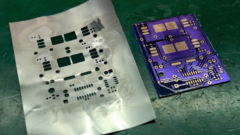
Sometimes it might seem as if your electronics are just jinxed. For [Niva_v_kopirce] it was the control board of his nephew’s RC car that kept frying the transistors. In situations like this, you can either throw it in the bin, invest your time in troubleshooting, hoping to find the error and try to fix it then, or get creative. He chose the latter, and designed and etched a replacement board.
Of course, etching your own PCB isn’t that noteworthy for the average Hackaday reader, although [Niva_v_kopirce] did go the extra mile and added purple solder mask to it, turning the stylishness definitely up to 11. This is also where it gets interesting, when you think of the solder mask as complementary layer for a solder paste stencil. Growing tired of manually applying solder paste, he thought to give a DIY stencil a try this time — using a beer can.
After cutting the can open and flattening it, along with some sanding, he transferred the cutouts from the solder mask onto it, and started etching holes in it. While the result may not be exactly precise, it did the job, especially for a homemade built.
Despite their convenience, stencils are still a rather exotic addition for hobbyists as they rarely pay off for a one-off project with limited SMD component usage. But maybe this was a new inspiration for you now. And if etching metal is outside your comfort zone, cutting plastic can be an alternative, as well as 3d printing.


Someone should sell a set of punches and dies in the various solder pad footprint sizes.
Cheap desktop laser engravers are the key here. You spray the sheet with paint, then laser the paint off, then etch with acid. It would be cheaper than a whole set of such tools.
Or cut directly in thick card stock for a disposable stencil.
Stock that thin, 3 or 4 passes with an engraving laser should go through it I would think.
You’ll char it, and the edges of the holes will crumble.
I just tried it on my 4.5 watt ortur and it cut it just fine in 2 passes at 80 percent power
Do you even need the paint? Drink can material has a plastic coating on it already.
Dark paint so the laser doesn’t get reflected.
Coke Zero?
You could probably use standard crafting / office hole punchers. Beverage cans aren’t that thick.
Rubber stamp, anyone?
LOL, niva_v_kopirce :D
That by the way means “Blue cheese in copier” :D
czech or slovak word? ;)
I’m czech but it’s probably the same in Slovak :)
Yeahhh! The Czechs are in the building!¡!
Or just, you know, solder the freaking thing with a soldering iron.
Nothing on that board looks exotic or difficult.
It looks to me like solder paste and a solder mask would be more work than just getting out the iron and a roll of solder.
Sometimes, you do it just to see if you can so it.
Once the current gets above a few amps, hand wired motor controllers get into trouble with the parasitic inductance associated with the wiring. It lets the smoke out of the transistors. Found this out the hard way.
That depends a lot on individual skills. Soldering small parts with stencil and paste can be substantially easier with shaky hands.
I’ve found that laser-cut paper works quite ok as a single-use solder stencil.
“if etching metal is outside your comfort zone”
If you’re etching PCBs, it isn’t. I use soda can material and the same toner transfer via heated laminator process as used for the PCBs. Ferric chloride etches aluminum very rapidly.
Do you just add a fully-opaque mask to the back?
That cool purple solder mask is just the photo resist filem left in plaace. I did that last time, looks better and does act like a solder mask to a degree.
I wonder why it “kept blowing transistors” and whether that got fixed.
Me too. I don’t see how a new PCB is a fix for that. I was expecting the beer can to be pressed into service as a heat sink.
When reading the original link, the issue was too high a voltage, when the battery was fully charged, which wears down the transistors over time. There seem to be also voltage spikes from motor coils, that had to be flattened using caps. How well that was done in the original circuit is not clear.
So the actual solution was classical error identification, and then making a new circuit more or less based on the old one, with some design improvements to fix the transistors being overloaded.
The creative part was about making the PCB, not the problem solution itself.