When the Raspberry Pi people launched their RP2040 microcontroller, it seemed as though it might be destined as a niche product for those areas in which the Pi has traditionally been strong. But during the global semiconductor shortage, it has remained almost alone among microcontrollers in having plenty of fab capacity to keep the supplies rolling. That, and its very vanilla set of ARM peripherals alongside those programmable state machines have thus seen it find a home in many places it might not otherwise have seen. Take the dual RP2040 motor controller from [Twisted Fields] as an example, would it have been more likely to have sported an STM32 in previous years?
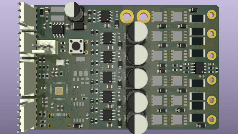
It’s been produced as part of the Acorn Precision Farming Robot platform, and it’s a fully open-source two-channel controller on a board the same size as a credit card. The schematic appears fairly conventional through a cursory glance at the PDF, but we know from experience that motor controllers are never as deceptively simple to get right as their circuit would lead the unwary engineer to believe. The heat dissipation, current, and transient handling all play a part in a successful design, and we expect this one to evolve to fix any issues it might still contain.
If you’d like to remind yourself about the Acorn farming robot, then take a look at our earlier coverage of the project.
Thanks [Mark] for the tip.


From the schematic it looks like it’s a dual motor controller with one RP2040. The “dual RP2040 motor controller” might need to be rearranged to be more clear.
It is dual core. ;-)
The RP2040 has one feature (or more accurately a lack of one) that may help keep it available for makers and open source projects. Unlike most modern microcontrollers, it has no code security features at all. That makes it unappealing to developers of closed source systems.
I’ve heard the RP2040 chip and the Pico dev-board were designed down to a price. I’ve been in the loop when IP (Intellectual Property) license pricing options were being negotiated with ARM Ltd. If memory serves the firmware security extension was a rather expensive option, but then again the target was not a Cortex-M core like with the RP2040. I also read somewhere that the reset button on the Pico board was omitted to reduce cost.
It’s entirely possible to write a custom encrypted OS on it, with the specific goal to be more secure, and use the hardware to checks itself more often for errors.
Encase the 2040 in thermal epoxy, so all company and os data remains secure, and harder for a hacker to pry into the system.
The epoxy would peel off with the solder mask, so our hypothetical hacker could still easily access all the pins on the QFN package.
In any case, the RP2040 relies on external flash, so all one has to do is read that flash out with any other SPI controller. As the RP2040 has no retentive memory whatsoever (except the boot ROM), it has nowhere to store a private key with which to decrypt a potential encrypted OS. Regardless, one would simply have to tap the SWD line and pull the code out via the debugging interface.
Instead, one could use an appropriate STM32 (or similar).
“part of the Acorn Precision Farming Robot”
I wonder if can be adapted to farming more than acorns?
B^)
@Jenny List said: “When the Raspberry Pi people launched their RP2040 microcontroller, it seemed as though it might be destined as a niche product for those areas in which the Pi has traditionally been strong. But during the global semiconductor shortage, it has remained almost alone among microcontrollers in having plenty of fab capacity to keep the supplies rolling.”
You are very right about that. But the quick RP2040 adoption has more to do with just availability. There are several good reasons:
A. There’s a stable and open-source development-board that uses the RP2040 chip, the Raspberry Pi Pico. The Pico is readily available today and it costs just USD $4.00 each in unit quantity.[1]
B. The RP2040 chip (133MHz dual-core ARM Cortex M0+ 56-VFQFN pkg) is readily available today, and at only $1.00 each it’s surprisingly affordable.[2]
C. Thanks to Earl Philhower and the existing RP2040 C/C++ development environment from the Rasperry Pi folks [3], today there is a good C/C++ RP2040 Core that plugs right in to the popular (love it or hate it) Arduino IDE.[4] The Pico works well with the Arduino IDE and the Arduino-Pico Core is well documented.[5]
* References:
1. RASPBERRY PI PICO RP2040 BOARD, 28,693 In Stock, Qty.-1 $4.00 ea:
https://www.digikey.com/en/products/detail/raspberry-pi/SC0915/13624793
2. RP2040 chip P/N SC0914(7), 92,502 In Stock, Qty.-1 $1.00 ea:
https://www.digikey.com/en/products/detail/raspberry-pi/SC0914-7/14306009
3. RP2040 and RPi Pico Getting Started:
https://www.raspberrypi.com/documentation/microcontrollers/raspberry-pi-pico.html
4. Raspberry Pi Pico Arduino IDE Core:
https://github.com/earlephilhower/arduino-pico
5. Arduino-Pico Documentation:
https://arduino-pico.readthedocs.io/en/latest/
There are a couple of other factors. They ordered a large run of wafers before the shortage, so they were in luck there. Maybe even more so is the lack of internal flash, which vastly decreases the amount of silicon needed for the MCU itself.
Not to forget the price!
I am even frustrated to see that “the most affordable solution to $x” became the RP2040 for many domains.
FTDI or other USB handling chips, dumb pin muxers, I2C pin dispatchers, dedicated timer chips, even most 8-bit micro controllers (!) are more expensive than the RP2040.
So many supposedly low-cost ASICs + 8-bitter MCU can be replaced by a more affordable RP2040 + PIO peripheral.
This incredibly amplifies the “in-stock” effect: wait for a pricier chip to get back in stock, or get the less expensive RP2040 now?
Of course, price is not the only thing to optimise a system for (power, certifications, speed/presence of a feature…).
Cool. Is there a firmware that it is supposed to run? I wonder how does it compare to odrive, moteus and vesc.
The problem is that VESC and Odrive do FOC. The problem is that RP2040 doesn’t have enough ADC channels for that. :-(
For what? To FOC you usually want 3 low-side shunts (3 ADC channels out of 8 in RP2040) for current sense, and some position feedback (encoder, Hall sensor) that often doesnt use analog link to MCU anyway. SimpleFOC library is supporting RP2040 so it can be done.
Hello I am the designer of this board.
You can do FOC with just an encoder, current measurement is not required. At least this is what some knowledgeable people were saying on twitter. They also told me that without current measurements for each bridge you can’t estimate torque. I laid out the board with one current measurement for each motor, so that would only give total power but not torque… or something. I’m not an expert on the control side. Anyway I’d like to be able to estimate torque. I had vaguely remembered that the Odrive only measures current on two of the three phases per motor. I double checked on one of my odrives and sure enough there’s only shunt resistors on two of the three phase legs per motor. I think the reason this works is that all three legs are tied together… or something. I really need to find a white paper to confirm the basis of this. I might just message Oskar from odrive and ask him to confirm as right now I just need to know how many phases to measure. And Oskar is a super helpful guy.
Anyway one other thing that came up is that the RP2040 has a serious bug in its ADC implementation. So I’m probably going to use an offboard ADC. But JLCPCB stocks a nice looking ADC for $0.50 that has two channels, so hopefully just two of those chips will do what I need better than the RP2040. By the way I think the RP2040 only has 4 ADC pins.
Anyway yep the plan is to use SimpleFOC!
Temp and other low priority sensors can go via the USB port.
RP2040 also does not support floating point operations in HW. STM32F4xx in VESC is Cortex M4F based and FPU coprocessor is fully utilized in VESC. (The FW is even compiled with hardfloat option.)
Hello! I am the designer of this board. We’re going to look at using SimpleFOC, which already has a port for the RP2040. I use VESC and Odrive in some other projects. Biggest thing is that this board is designed using all parts which are in stock in high quantities at JLCPCB, meaning anyone can order them assembled using the JLCPCB assembly service. My hope is that this will mean many people decide to fork the board and sell them, and that it will grow and change over time to meet the needs of the community. VESC is nice but it seems the original designer moved on to a much more expensive closed source option. And Odrive seems to be moving more closed source too. This board is intended to be completely open source. Long term I want to work with AliExpress electronics manufacturers to produce their own versions that are as cheap for them to make as possible. Already I am selecting Chinese brand chips for everything but the RP2040 and its required SPI flash memory. This should make it very easy for Chinese manufacturers to produce it at a very low price.
+1 internets for design for (cheapest) manufacture
Thanks for jumping into the chat, and for giving such a full description of your approach!
Is it an electric motor controller?
+1 for the noble goal of explicitly keeping everything open-source. There is nothing worse that seeing open-source projects going more and more closed as soon as they get some success.
Howdy Taylor,
I’m a maker from SA, do you have somewhere we can follow your work on this? And, this is a guess, I think the vesc and odrive don’t shunt the third leg because this is essentially a ghost phase generated from the caps. Similar to a static phase convertor where you use the caps to generate the third phase from single phase power.
And thank you for this project, I have been pondering how to accomplish this since the launch of the 2040, so will begin tinkering.
I’d be psyched to have some of these fabbed and assembled (5 to 10) but I’ve never worked with JLCPCB before. Are the files included in the git repo sufficient (without extra software or export tools) to place an order for assembled boards? If not, do you know of a tutorial for whatever middle steps there are?
This looks like the perfect board to replace a couple VESCs in a new version of a hoverboard wheel based robot (since the new owners of VESC have gone all evil and closed source).
Wouldn’t a couple of cheap, hackable, hoverboard motor drivers have fit the bill just as well? They have ARM micros onboard, but you could even use them “dumb” and use an RP2040 for your app. code. Just a thought.
Unfortunate about the isense Kelvin routing, but that can be fixed in the next turn.
Can you please clarify, I’d like to learn more about this…
I’m always interested in motor controllers, and this project is available as a KiCad project, so I had a look at it.
I like the use of the XL7045, with both a quite high input voltage (upt 80V) and output current limiting.
I would have preferred to put the EG2131 (and surrounding parts) on a hierarchical sheet. It’s a bit fiddly to use hierarchical sheets to see what I/O pins are connected where, but it ensures that all 6 motor driver circuits are always identical, because only one is drawn.
I prefer to use the “european resistor” style, not (only) because I’m an european, but because the room inside the resistor can be used to put the value of the resistor, which saves room on the schematic and makes it look “cleaner”.
With high currents on PCB’s, the GND connection is always troublesome. For example, if the “Power GND” gets loose, is there any chance of the motor return current flowing though the USB or other GND wires (which is likely to melt them)?
I’m not sure if adding external skottky diodes to the MOSfets helps in any significant way. Skottky diodes start conducting current at a low forward voltage, but the voltage often also rises relatively quickly with the current. In old generations of power MOSfets, the internal diodes were quite bad, but in newer generations these have often improved a lot. These diodes are also only connected to the rest with a thin 0.5mm via’s and in some cases 0.3mm wide tracks. this is too thin for high current.
Having only a single shunt resistor for all three motor phases does limit the software algoritms you can use on them. Software apparently is not written yet, but having an idea of what you want with this before sending the Gerbers out is probably a good idea.
What is the expected motor current for this thing?
2mOhm is a quite low shunt resistor value, and the LM358 also has relatively big offsets (but it’s cheap).
The minimum I would do is to add an extra resistor to turn it into a differential amplifier. Using the same value resistors for both inputs also minimizes the offset voltage generated by the bias currents, and reduces extra errors caused by GND currents in the PCB (If combined with an appropriate PCB layout). With an extra resistor and differential amplification you can also choose the feedback point in such a way that errors due to voltage drop over PCB tracks is minimized. (These are the missing kelvin connections that [Michael Henderson] refered to.
What is the “RUN” pin 26 supposed to do?
Apparently the annotation changed after writing some comments in the schematic such as: “Make sure R4 and R5 are …”
The ~LIN pins of the EG2131 have 200k pullups to 5V. Is that ok with the RP2040?
Is the GND pad in the center really the only GND connection of the RP2040? That is … unusual at the least.
For the PCB:
I only see a single GND layer. For high power PCBs, more copper is better because it distributes heat better through the PCB and thus it works better as a heatsink, and it also reduces stress by uneven thermal expansion.
There are also quite big holes in the GND plane, Especially the two long sections of the “A1” and “A2” nets, and the big gaps because of long rows of via’s near the mictrocontroller. This is not optimal, but can also be changed easily. (The clearance to the via’s is also quite big).
Quite a number of PCB tracks are only 0.15mm wide, which is starting to become troublesome for PCB manufacturing, while there is plenty of room for wider tracks.
You can also further reduce voltage drops over the PCB by doubling up copper layers. for example between the MOSfets and the motor outputs.
I see no mounting holes on the PCB, is this intentional?
You also have a lot of high power wires in big pads, and I assume these are supposed to be soldered.
However, soldering stranded wires without using any strain relief is a serious point for failures. The wires tend to break right at the point where the solder stops. It is a much better design to put the motor wires directly in between the MOSfets, then bend the wires and use cable ties or glue to fixate them to the PCB a few cm further.
The connections between the MOSfets and the motor pads are 7mm wide, but with a standard copper thickness of 35um this is still only 0.25 square milimeter, and this is not very much. Inner layers are sometimes also only half this thickness and you have to make sure you order the right stuff when ordering PCB’s.
The tab of the NCP1117 is also connected with thermal via’s. What is the expected dissipation of this regulator?
This is good information for _all_ PCB designs, thanks paulvdh!