
Four years ago when the idea of a pandemic was something which only worried a few epidemiologists, a group of British hardware hackers and robotic combat enthusiasts came up with an idea. They would take inspiration from the American Power Racing Series to create their own small electric racing formula. Hacky Racers became a rougher version of its transatlantic cousin racing on mixed surfaces rather than tarmac, and as an inaugural meeting that first group of racers convened on a cider farm in Somerset to give it a try. Last weekend they were back at the same farm after four years of Hacky Racer development with racing having been interrupted by the pandemic, and Hackaday came along once more to see how the cars had evolved.
Probably The Most Fun You Can Have With Five Hundred Quid

We’ve mentioned Hacky Racers and Power Racing enough that many readers may be familiar with them, but to recap, the rules governing the series specify a maximum length and width of 1500 mm and 900 mm, a 2-horsepower power limit enforced by appropriate fuses for the voltage employed, and a £500 (around $600) budget limit. In keeping with the Power Racing inspiration many of the vehicles sport creative bodywork designs, and the result is a field of cars with top speeds somewhere between 15 mph and 20 mph (around 30 km/h).
At those first Hacky Racer meetings back in 2018 there was a mixture of power plants. There were a few 24 V DC transaxles from mobility scooters, some DC power plants from golf buggies, and the faster vehicles featuring 2 hp brushless auto rickshaw motors. Most chassis designs were modified from donor machines, and motor controllers were commoditised Chinese modules. Thus it’s interesting to see how a few years of development has evolved the formula. Four years later the newer machines all have custom chassis designs, there were none of the mobility or golf-based DC motors on show, and the rickshaw motors have been joined by converted car alternators. It’s clear that it’s in these last power plants that the most development is proceeding, so it’s worth taking a closer look.
Pushing The Limits With The Cheapest Brushless Motor Of Them All
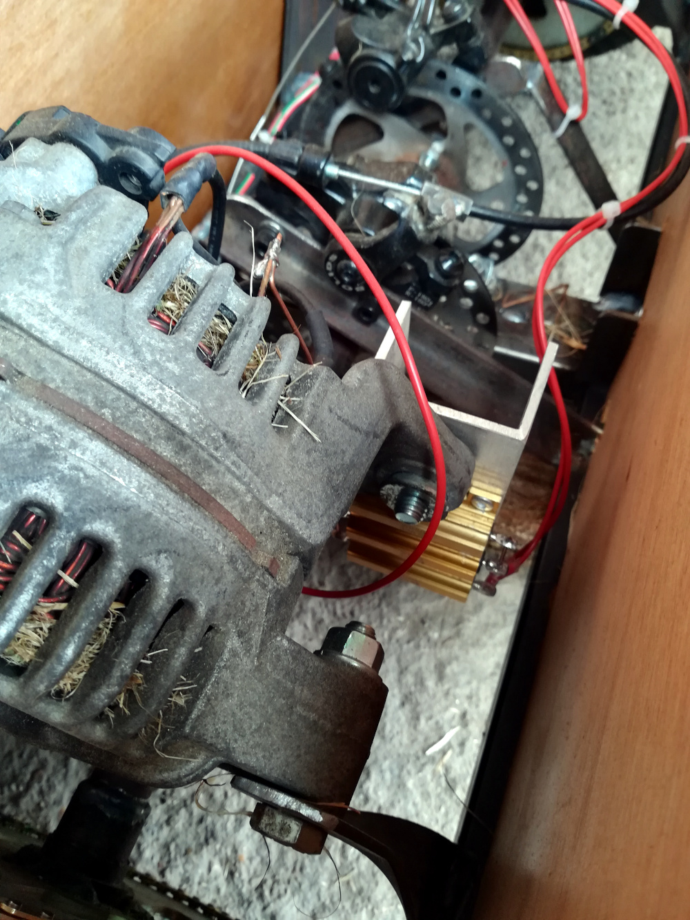
We covered the conversion of alternator to motor back in early 2020, and from that we know they require a DC bias for their field winding as well as the 3-phase AC from the motor controller. Experimentation has shown that this winding requires between about 2 A and 5 A depending on the alternator, but it’s in managing this figure that some of the most interesting technical developments lie.
In a brushless motor the stator is a magnet, and it spins in a field created by a set of coils spaced around it. Like most smaller brushless motors the rickshaw motors have a permanent magnet as their rotor, which works well but is prone to overheating. The alternators have an electromagnet with a set of brushes as their stator, and this electromagnet forms the field coil. The more current in this coil the more magnetic field there is, and thus the more torque the motor can produce. More magnetic field also means more back EMF though, and since the motor controller must counteract this back EMF there’s a tradeoff in that the top speed is lower when the current is higher for more torque. The interesting developments with these motors therefore come with variable field current to select the desired combination of torque and top speed.
The simplest method for providing field current is to place a suitable resistor in series with the field coil and hook it up directly to the battery. This seems to be the preferred route of the moment, with one machine using a pair of relay-selected resistors for different motor torques switched in and out by means of a button on the steering wheel. This first-generation field control is being displaced by active electronics, with one racer using a small DC motor controller to power the coil and another experimenting with a buck converter that will eventually map the field current for the best torque at a particular speed.
It’s clear then that the Hacky Racers are pushing the development of their formula, and that they’re doing so while retaining the have-a-go character of the event is to their credit. Motorsport is blighted by so-called chequebook racers, and in this respect Hacky Racers join lawnmower racing as the antidote to formulas which take themselves too seriously. Meanwhile the development of car alternators as brushless motors has huge value for anybody experimenting with small-scale electric traction, so we look forward to more refinement of those techniques.
As we close this piece it’s worth mentioning the venue that hosted the Hacky Racers as they let their hair down. North Down Orchard is a working Somerset cider farm with camping facilities and an excellent cider barn. Some of us here at Hackaday are connoisseurs of good quality real cider, and we wholeheartedly enjoyed North Down’s cider as a particularly welly-crafted example of the art. We hope the Hacky Racers convene there again, and we look forward to bringing you whatever new technical advancements they’ve made in the intervening time.


Great Post. Back in 1991, I helped build an electric go-kart which used 2 salvaged Sinclair C5 motors for front wheel drive. There is not much documentation left apart from this ancient Geocities Web page. http://www.geocities.ws/kenboak/Elcars.html
This may be worth salvaging…
Visit this link at your own risk. I got a flash of of content, then popups with fake claims of “virus infection” and immediate redirection to download stuff.
Same. Definitely something fishy going on there. At least it showed the content for a few seconds.
I got something trying to install an extension, and popups where the content was mis-configured.
Adding a S did help to get to the content:
https://www.geocities.ws/kenboak/Elcars.html
Also:
https://xkcd.com/2634/
Well HaD seems to have eaten my comment.
Try:
https://www.geocities.ws/kenboak/Elcars.html
https://web.archive.org/web/20121220173630/https://www.geocities.ws/kenboak/Elcars.html
https://web.archive.org/web/20121220173828/http://www.geocities.ws/kenboak/avt100.html
The other links, with or without an s are decidedly not NSFW
I like the alternator, I may in fact have multiple and a chinesium brushless controller XD
“North Down Orchard is a working Somerset cider farm with camping facilities and an excellent cider barn. Some of us here at Hackaday are connoisseurs of good quality real cider, and we wholeheartedly enjoyed North Down’s cider as a particularly welly-crafted example of the art.”
After a mix-up once in an American bar, I feel it is worth mentioning to our US friends that we are talking alcoholic cider here!
Is “welly-crafted” a thing or a typo? Curious minds want to know…
Wellies would be the stereotypical rural footwear known elsewhere as Wellington Boots, gumboots, rain boots, rubber boots, hunters…. Welly-crafted (used intentionally) would connote to me that it was farm made scrumpy, not your supermarket PET bottle woodpecker.
Scrumpy? Woodpecker? Sounds like your colloquialisms are getting in the way of your communications. Also, from context, it was definitely a typo (and no results for “welly-made” appear in DDG except a die-cast car manufacturer).
And at least in the US, I’ve never seen cider in a PET bottle (like beer, it’s always in glass or aluminum).
Oh, excuse me for using colloquialisms so obscure that no miniscule amount of googling would illuminate the black depths of your ignorance, at https://en.wikipedia.org/wiki/Scrumpy all https://en.wikipedia.org/wiki/Woodpecker_Cider
That’s “minUscule” – HTH =]
Yes, welly-crafted is a thing down here!
(alcoholic) cider has made a come back in the US (back when we were the colonys it was the main thing going)
so at least on the coasts
ordering cider is completely normal now
Johnny Appleseed
(Apples grown from seeds are generally bitter, so he was promoting alcohol production)
North Down Orchard?
I forgot that place existed and I live local to it :(
Are you allowed a LN2 bath for the fuses? :-D
“Are you allowed a LN2 bath for the fuses? :-D”
A true hackaday Question :)
Cap
It seems like this would be a good place for a (big) constant current LED buck regulator, many of which have the regulation current set by something that could be adjusted. It’s harder to find a 5A one but there are piles of inexpensive 2-3A CC LED drivers out there, some of which are specifically designed for microcontroller control of the output current. That’d make implementing something like a maximum power point tracking algorithm but tuned for car performance, a lot easier.
I’m a KISS kinda guy, and I’m into RCs, so I’d start with a Hobbywing 1060 ESC and a simple servo tester. Well under $50 and you have something rated for 60A that you could adjust very easily and figure out where the sweet spot was for each driving condition right off the hop. If you wanted to get crazy, you could go back and have throttle be an input to an Arduino and drive the ESC’s input to match what you’ve found to be ideal with the servo tester.
Are ESC’s current-control or voltage-control? I thought they were either voltage or PWM-voltage-approximation, and I’m not sure that’s the right control scheme for the field winding of an alternator.
If you’re running a hobby motor ESC without hall sensor feedback, it’s going to be block commutated which means it switches the battery voltage directly into two of the motor phases and uses the third to measure out the resulting back-emf (motor phase). PWM is used to vary the on-time of each commutation step to vary the motor power. It’s a very dirty control scheme that makes a lot of noise and doesn’t run very efficiently or smoothly, especially at low speeds.
The next step up is block commutation with sensors, which uses all the three phases for power but is still more or less on/off switching with PWM. It’s more efficient and gets more power and torque out of the same motor, but it’s still a bit noisy.
Then comes field oriented control which measures the phase currents as well and calculates the rotating magnetic field vector, then applies a measured amount of current into each three phases to produce an orthogonal excitation vector. It basically makes “true sine” three phase power with voltage AND current control in lock-step with the rotor’s position, which makes for smooth torque at all speeds up from zero.
I need to find one of those (F)ield (O)riented (C)ontroll-(ERS). Looks to be really handy…
When applied to induction motors, Field-oriented Control is called “Vector Control”.
The difference is that Vector control measures and estimates the field that was induced in the rotor to see where it is actually pointing, and then calculates a suitable phase delay for the three phase currents so you get a torque generating field exactly 90 degrees in advance of the rotor field. It controls both the rotor field and the torque generating field at the same time, so it can drive an induction motor from 0 RPM up almost like it was permanent magnet motor. It’s kinda neat watching it turn a 2 kW industrial motor at less than 1 RPM like it was a servomotor.
With a permanent magnet motor, the rotor field is already known from the rotor position because it’s fixed to it, so the computation becomes simpler – still, as the field reacts to the currents being applied and shifts out of alignment, more advanced FoC controllers try to adjust for that as well.
With the alternator turned into a motor, what you have is Vector Control because you can choose the rotor excitation current and measure the shaft angle to calculate where the stator field should be pointed at. The concept is very simple – the math just gets complicated because you convert from rotating vectors into DC to do all the feedback control algorithms (basic PID), and then convert the result back into a three-phase rotating field.
See compound wound DC motors.
Large DC motors do not use permanent magnets either – they’re excited by a parallel (shunt) or a series field coil, or a combination of the two (cumulative or differential compounding). With suitable compounding, you can achieve a flat power or torque curve across the entire speed range. You can also make a motor that will spin faster and faster without load until it explodes.
With a modified alternator, you can’t split the field coil into series and parallel sections, so you have to emulate compounding. You first apply a constant field current (shunt field), then measure the motor current and apply plus or minus the variable motor current (series field). Varying the proportion of the simulated shunt and series currents will give you the desired power and torque curves.
“In a brushless motor the stator is a magnet, and it spins…” A stator doesn’t spin.
“The alternators have an electromagnet with a set of brushes as their stator,…” “Meanwhile the development of car alternators as brushless motors…” Only if there’s a model of alternator that uses a permanent magnet rotor rather than electrified via a pair of brushes and slip rings.
Is there a more appropriate or commonly used term for the type of dc motor that you get from converting an alternator?
Calling it a “brushed dc motor” would be equally confusing even though it’s literally accurate. “brushed field current”?
For their price & power & ubiquity, car alternators are a vastly under-used resource in hacks.
“In a brushless motor the stator is a magnet, and it spins in a field created by a set of coils spaced around it.”
Absolute n00b here. Doesn’t a rotor spin (rotate) and isn’t a stator static, hence the names?
Wikipedia: “An electric motor develops torque by keeping the magnetic fields of the rotor (the rotating part of the machine) and the stator (the fixed part of the machine) misaligned. “