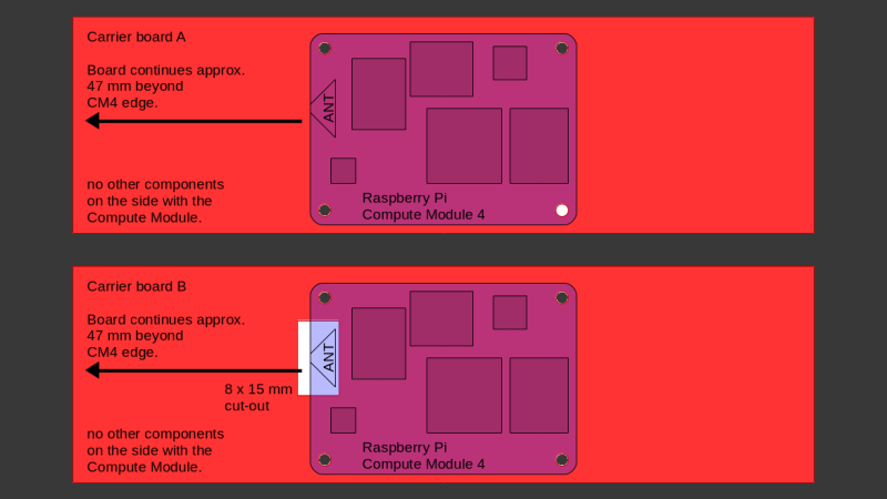
The Raspberry Pi Compute Module 4 has a built-in WiFi antenna, but that doesn’t mean it will work well for you – the physical properties of the carrier board impact your signal quality, too. [Avian] decided to do a straightforward test – measuring WiFi RSSI changes and throughput with a few different carrier boards. It appears that the carriers he used were proprietary, but [Avian] provides sketches of how the CM4 is positioned on these.
There’s two recommendations for making WiFi work well on the CM4 – placing the module’s WiFi antenna at your carrier PCB’s edge, and adding a ground cutout of a specified size under the antenna. [Avian] made tests with three configurations in total – the CMIO4 official carrier board which adheres to both of these rules, carrier board A which adheres to neither, and carrier board B which seems to be a copy of board A with a ground cutout added.
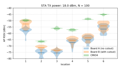 After setting up some test locations and writing a few scripts for ease of testing, [Avian] recorded the experiment data. Having that data plotted, it would seem that, while presence of an under-antenna cutout helps, it doesn’t affect RSSI as much as the module placement does. Of course, there’s way more variables that could affect RSSI results for your own designs – thankfully, the scripts used for logging are available, so you can test your own setups if need be.
If you’re lucky to be able to design with a CM4 in mind and an external antenna isn’t an option for you, this might help in squeezing out a bit more out of your WiFi antenna. [Avian]’s been testing things like these every now and then – a month ago, his ESP8266 GPIO 5V compatibility research led to us having a heated discussion on the topic yet again. It makes sense to stick to the design guidelines if WiFi’s critical for you – after all, even the HDMI interface on Raspberry Pi can make its own WiFi radio malfunction.


What about instead of making a cutout trying to get it to help/boost the signal?
actively boosting in both directions might be more expensive than buying a WiFi chip and putting that on your board someplace else.
an passive coupling to the CM4’s antenna might be interesting but way beyond my abilities to design. I think it would be complicated and it’s kind of why wifi modules for laptops use a coax connector instead. It’s much more controlled and wider band and simpler than the hack I suggested.
Oh yeah, I’m on board with you here: in most cases, leave the WiFi stuff to specialists!
I like the idea of passive coupling, but it is most definitely beyond my own design capabilities too… XD
That being said, even if your cutout idea only adds a few dB in most use cases, I think that’s definitely still worth it. Overall, people taking a few more minutes/hours thinking about where they place their antennas and actually run some basic tests is the important thing to remember from this post! It shouldn’t be an afterthought once the board is fully designed and it’s too inconvenient to improve WiFi signal strength/quality.
To be fair it’s a hindsight 20/20 sort of thing. Someone with experience with board layout and RF modules may have anticipated this. But everyone else would have had to have done it wrong the first couple of times. (because clearly this is not being taught in school)
I honestly have faced more fundamental problems from boards intended for production use. Like the wrong I2C pull-ups or wrong kind of level shifters for RS232/UART control lines. (just rx/tx working isn’t really good enough if you want to say you’re RS232).
I strongly recommend module designers publish a spec for the layout. not just for connectors and maximum Z height of components underneath the module. But things like ground plane cut out. Expecting every layout engineer to come to the same conclusion on their own is a bit unreasonable of us. :)
Adding to this and in particular to the CM4 was their choice in mating connectors. These connectors are problematic to mount properly (two 100pin 0.4mm pitch connectors with no locating pins). In fact the connector manufacturer (Hirose) themselves stated that two parallel connectors should not be used, as the space to space x tolerance needs to be 0… and the y is to be +/- 0.01mm. Even using high quality PnP machines will find this challenging over time given that all equipment has placement variability/accuracy along with the placement/accuracy of the connectors on the module itself. Hand placement is possible, but is time consuming and can also have issues. A hardware design checklist would have been very helpful and should indicate a number of these items and/or things to be aware of.
A proper structure under the antenna will be able to couple in >50% of the power. Then, in theory, you can route it to a bigger antenna. It will require a lot of simulation time to design this though, an external wifi chip will be way simpler.
A cutout will only allow a small portion of the wave to pass, so it makes sense that it only makes a small difference.