When interfacing with the real world, there are all kinds of sensors available which will readily communicate with your microcontroller of choice. Moisture, pH, humidity, temperature, location, light, and essentially every other physical phenomenon are readily measured with a matching sensor. But if you don’t have the exact sensor you need, it’s sometimes possible to use one sensor as a proxy for another.
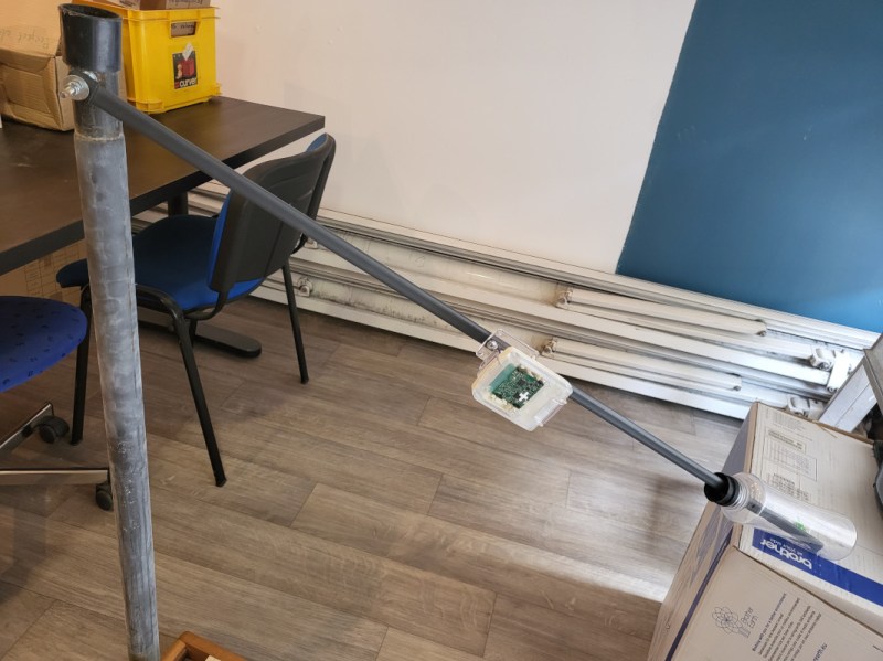
[Brian Wyld] needed a way to monitor the level of a remote body of water but couldn’t use a pressure or surface-level sensor, so he used a sensor typically intended for geolocation instead. This particular unit, an STM-type device with a built-in accelerometer, is attached to a rotating arm with a float at one end. As the arm pivots, the microcontroller reports its position and some software converts the change in position to a water level. It’s also paired with a LoRa radio, allowing it to operate off-grid.
Whether there is a design requirement to use an esoteric sensor to measure something more common, or a personal hardware limitation brought about by a shallow parts drawer, there’s often a workaround like this one that can accomplish the job. Whatever the situation, we do appreciate hacking sensors into other types of sensors just as much as anything else.


Sorry to nitpick, but it’s wrong to write that it senses position: it senses *orientation*, and that makes a lot more sense: The project uses an *accelerometer*.
It’s not the change in position (you can of course integrate acceleration twice to get position, but you’ll be integrating the errors!), but the change of angle of the arm that’s being sensed. And that’s an immediate reading from the accelerometer, which senses in which direction relative to the sensor gravity pulls.
There might be confusion as the board and case are from a discontinued product that was for indoor positioning… the project uses the accelerometer as you noted which is used to measure inclination wrt. the earth in this case.
Since we’re nitpicking, accelerometers can’t immediately read “change of angle”. They can instead immediately read acceleration along an axis. Objects on the surface of the Earth can’t freely fall through the curved space caused by gravity, and are instead being constantly accelerated to “stay in place”. So, an accelerometer will detect a varying component of that acceleration depending on the orientation if its axis relative to it. When you move the accelerometer, though, you’re also accelerating and decelerating it, and the readings from it will reflect the net acceleration. In order to determine angle relative to the ground, you need to combine the acceleration data with an assumed kinematic model (I’m mounted to a stick on a fixed pivot) so that you can collect enough time series data to estimate the angle with some confidence.
Gyroscopes on the other hand do directly measure changes in angle, but only accurately over a relatively short time.
Why overcomplicate something that is easily done with some basic trigonometry?
Using a 3-axis accelerometer (ignoring any forces other than gravity) you get a vector whose length matches the gravitational force that is always pointing to the ground.
To obtain the angle, you’d first calculate the dot product between that vector (after normalisation) and a reference direction vector (implied: you need to attach the accelerometer with its axes suitably aligned when the rod is either at the top or the bottom). Depending on how you oriented it, you’d get a value between [-1, 0] or [0, 1], which you could feed directly into arcsin/arccos to get the angle.
Drift. . all such sensors have drift. It will work for the first moments, but accumulating errors will defeat this project. A good old quality potentiometer would do a far better job !
Drift is not a problem when using accelerometers to determine angle, no integration is required. When using gyro’s it would be a problem. Then integration is required to get the actual angle.
i have no idea how stable a mems accelerometer is so i can’t comment on the first part of your comment. but if we’re nitpicking based on anticipated failure modes, i’ve got news for you about potentiometers, especially in outdoor installations :)
this armchair engineer votes for optical encoder
Every car gas gauge I have ever seen has used a really simple pot system, as there is very little to go wrong, and in this case the pot being at the arms pivot, could be protected. Encoders are OK but they take power and have more modes of failure. In other, non gas tank, places I have seen ultrasonic and conductivity. IMHO ultrasonic has way too many places it can fail and takes even more power than optical. Conductivity is interesting but needs more electronics than is obvious so you don’t eat the probes and you need to know the characteristics of the stuff you are measuring.
Fuel level floats in fuel tanks don’t have to worry about the outside environment full of salt and water just waiting to corrode any thing it touches. They’re nice and protected by a bunch of fuel.
No drift, but maybe unwanted noise from movement. I vote for a Hall sensor – easy to get analog signal, can be completely sealed
Drift can be countered by self-calibration. If the level is guaranteed to periodically go to zero or maximum, you can put an end sensing switch to detect that condition and recalibrate the accelerometer appropriately.
@Ono said: “Drift… all such sensors have drift.”
Yes, but there are relatively simple ways to (for practical purposes when properly applied) zero-out the “drift”.[1][2]
1. Kalman Filter
https://en.wikipedia.org/wiki/Kalman_filter
2. Cascaded Integrator–Comb (CIC) Filter
https://en.wikipedia.org/wiki/Cascaded_integrator%E2%80%93comb_filter
Luckily for everyone, the g-vector (gravity) does not tend to drift.
Well, I have not experienced any drift with a mems accelero, and no calibration is required… certainly during my static tests at different angles the values remain very constant…
Also the aim was to use these available boards, and not to have to add on any external electronics (which would need waterproofing etc!)
You use a 3D sensor that measures the acceleration (in this case from gravity) in x, y and z. Then you can comoute the angle that represents down, i.e. to the center of Earth.
So zero drift but a small error if there is some waves on the water that makes the arm angle oscillate a bit.
If the goal is how far the float has lifted wouldn’t some sort of potentiometer (digital or otherwise) at the pivot point be a bit more of a direct solution than an accelerometer?
Perhaps more direct in an intuitive sense, but it’s a moving part that needs to be protected from the elements. It would be no more effective of a solution but more prone to failure.
And that’s the reason this is often solved with an optical potentiometer – they can be sealed and there is no magnetic surface or contact that will wear out.
The article is formulated as if a moisture sensor would be the normal solution but a flotation device really is the easiest and most common – the car industry has used such sokutiins for 100+ years. It’s harder to use ultrasound or optical beam to measure the surface and make it weatherproof. An optical beam means a lens that can fog up or get dusty and a ultrasound sensor can also fog up.
This is clever!
A common way to measure levels in tanks is ultrasound.
Yes, but the project had to use the available board… and needed to be waterproof using the available casing!
So I recently had to abandon using a low cost ultrasonic sensor to measure tank level. In cold weather, the high humidity in the tank would condense on the sensor and cause a large droplet on the sensor face. This caused false readings, often for days at a time. The sensor was supposedly waterproof but was probably designed for being horizontal where the water would fall off, not hang there.
I’m sure better sensors exist but they would have been hundreds of dollars more expensive.
Maybe a power resistor could be added to boil off the condensate.
It seems to me that cleverness comes from finding the simplest practical solution to a problem as opposed to figuring out how to make the most complicated one available work. Just my opinion.
While reading this post I got another idea that works and can be suitable for some situations.
You take a pipe (metal or pastic) and seal it on both ends (It could also be a solid rod) and then put it vertically in some tank. Then measure the buoyant force wit a loadcell.
An advantage is that all electronics can be above the water, but a disadvantage is that stuff sticking to (groing on) the pipe (rod) will change it’s weight and buoyant force.
Recently I had the need to develop a sensor system to measure the water level in my swimming pool, so I connected a rigid plastic tube to an Adafruit MPRLS air pressure sensor, which is interfaced to a Pico W. This reports a oressure reading to a Raspberry Pi 4 over MQTT once every three seconds (excessive, I know) and is both logged and displayed on a graph.
Of course, the atmospheric air pressure must be accounted for, so I added a second MPRLS sensor without connecting the air port to anything, thus measuring atmospheric pressure. I take this reading and subtract it from the first to get an indication of water depth level.
This setup has its problems (temperature and humidity sensitivity) but by and large, I can get some excellent information. For instance, I can determine when the pool pump turns on within a minute based upon the slight water level drop. The system is certainly more sensitive than what can be perceived by the human eye, which is exactly what I was going for.
You can do with a straight pipe with a floating reflector inside the pipe. On top of it use a laser distance sensor. Make sure the even out the pressure difference.