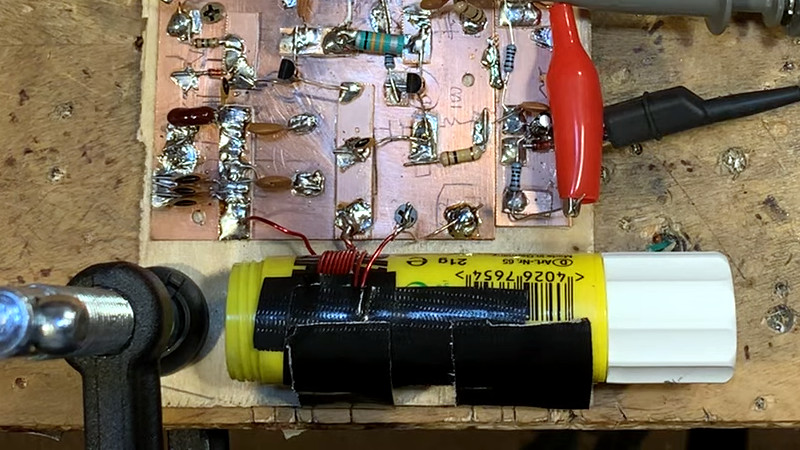
For over a century now, radio amateurs have made tuned circuits using a coil of wire and a variable capacitor. In recent decades the supply of variable capacitors has dwindled, as SDR technology has supplanted the traditional tuning capacitor. No more tuned circuits for the radio amateurs? Not quite, as [Bill Meara N2CQR] shows us in the video below the break by making variable inductors using permeability tuning. This is hardly high-tech, the major component is as simple as a glue stick.
A permeability tuned inductor has a core that is moved in and out of its center by means of a screw. A glue stick has a glue core on a lead screw from a knob at its end, so an old glue stick with the glue replaced by a ferrite ring makes a reasonable permeability tuned former. The coil is wound on its outside, and when assembled into an oscillator it gives a useful tuning range. This is hardly a new idea as permeability tuning could be found in car radios and TV tuners among other applications back in the day, but it’s still a good trick to bear in mind.
We’ve featured plenty of Bill’s videos before here at Hackaday, most recently tracking down an unusual early TV.


if transformers were tuned this way in am radios
“if”?
They certainly “were”!
B^)
if = Intermediate Frequency
IF = Intermediate Frequency
B^)
But the problem is, the core goes up and down. Nothing’s to stop you from using a coil with a core that tunes it, but your knob will move to and from the front panel.
In the sixties there were some projects about making PTOs, Permability Tune Oscillators. Lots of mechanical work. I think if you adjust the winding, you get vetter linearity. One used a ten turn counter, for a pot, as the dial.
I just used a surlus coil intended for car radios. Just rewound the coil. But those are long in the past. I did get a bunch of Collins PTOs, replaced the tube with a Jfet, and all was well.
I had an old surplus FM tuner module which had 6 ferrite slugs fixed onto a tuning sled. Adjusting the tuning shaft moved the slugs in or out of all the tuning and oscillator coils in the front end at once. Each slug was affixed to the sled on a slim brass threaded shaft. Alignment was performed by adjusting the position of the slugs relative to the sled by loosening a locking nut and twisting the shafts via a slot on the end, then retightening the locking nut. It sounds ungainly but it was as smooth as silk.
Of course, there’s nothing to stop you using the bolt trick from a few days ago, using two of these back to back with different pitch threads, to make very fine adjustments.
Personally I’ve used these as linear actuators before by adding a geared motor. I even attached one to a plastic syringe a while back as an experiment. I added a conductive plate to the plunger in the form of aluminum foil and another behind the nozzle. Using aa second syringe filled with an electrolyte, I made an electrically actuated variable resistor that was fairly well isolated. No doubt something like that could also be used to make a variable capacitor.
Perhaps wrapping the body of a glue stick in foil, then an insulator, then adding another conductor that folds back on itself, actuated by the center mechanism to move the outer conductor. It would be quite compact and have a good surface area for it’s size. You’d essentially just panel mount it like a large potentiometer.
There’s a similar old Trick.
The Modification of a Potientiometer (“Poti”).
Open the Potentiometer, remove the Graphite, then attach a Ferrite-Ring with a Paper/Scotch-Tape and a Wire-Coil made of Copper-Wire in such a Way it becomes the Surface which the Potentiometer’s Swiper-Device/Grinder-Device touches.
To make this work, the Copper-Wire must be blank on the right Side, of course.
Thanks! I love reading about engineers repurposing everyday objects. Alas, I couldn’t find Bill’s video on “tracking down an unusual early TV.” I guess YouTube has a ways to go on its search engine (or I don’t know how to search within a single channel).
Shortage in variable caps? There’s gotta be a way to 3d print them with some kind of impregnated filament.. There’s electrically conductive PLA out there. Rather bad conductor at 2-3 kΩ every 10cm at 1.75mm diameter, but might could work with the proper geometry.
If only conductive planar materials already existed, that plates could be cut from without having to 3D print them.
Sorry, did I say that loud enough, not sure it came over the mallet blows as you massaged your solution to fit the problem.
I think it’s just a trend. Someone tried a PTO, and others jump on. Nobody’s going back to dig out the PTO article or two in 73 in the sixties, and maybe one in QST.
“Nobody’s going back to dig out the PTO article or two in 73 in the sixties, and maybe one in QST.”
I’m not sure. Since 73 Magazine and QST magazine are being archived/online accessible, there’s a whole new generation of new readers.
In some forums, I noticed how old articles about the original 8s SSTV format were being discussed.
I think that’s because technology has evolved so far, or rather became so overcomplicated, that people have an interest to learn about “the old times™”.
They want to know how things started with such primitive apparatuses.
Sputnik, the Apollo capsule, the original Space Shuttle, the MIR, or their documents/films/etc, will still be admired with deep respect, even in centuries to come. These things aren’t forgotten, as long as people remember and care about them.
Same is true for the vintage computer hobby, I believe.
There’s a fascination among young people to learn about prehistoric digital technology. Dinosaurs are cool, you know?
On YouTube in the comment section, kids age 7+ do discuss the Atari 2600 and the Nintendo NES.
And they still enjoy playing these old games.
Some of which are older than me, even.
Vy73, 55
Would be easier to just print the parts that are supposed to be insulation/spacers and cut some sheet metal for the capacitor plates. Also less troubles with overhangs!
I’m surprised no one had mentioned the Variometer Coil yet.. :)
http://www.jogis-roehrenbude.de/Variometer.htm
Billy Cheung’s variometers in his “credit card crystal radios” are cool and have been featured on Hackaday.
https://hackaday.com/2020/06/01/credit-card-chip-used-to-make-crystal-radio/
An excellent idea- repurposing glue sticks,etc for VFO’s. The use of a T50-7 (30ppm/°C) is
an excellent start. T50-6 at 35ppm/°C is a small compromise. Always have the capacitors to deal
as well as the effect(s) of the active element. NPO/COG or NPQ caps .
A stack of these toroids glued together will make for a longer travel through the inductor.
Just some suggestions from a really old homebrewer:
1) Rather than a Hartley, try an an oscillator topography that uses an untapped inductor. Reason:
the feedback ratio will change as you insert the permeable core . Not so with an an untapped
inductor. I suggest a Franklin VFO. That type will reduce the temperature effects of the active
element(s) by reducing the coupling to the resonator. Lots of examples out there. Google it.
Yeah, it requires an extra transistor and it needs buffering because the output is low-ish, but do you
want to called out on 40 CW for running a “Drift-o-Matic”? Didn’t think so. It works with two BJT’s or two FET’s or whatever is in the junk box. Keep the bias current low to reduce heating.
2) Buffering the oscillator will help you when you connect up a frequency counter. The test cable TCC and TCL can add to the drift measurement. You thought you had a stable VFO, until 3 feet of RG-58/U pulled the frequency .
3) All the other things you have heard when building a stable VFO apply: No DSB PCB (use SSB with air-spacing!), solid voltage regulator like a uA723C, die-cast box, keep the heat out, put your power amp in another case (unless you Phase-Lock). I had to use temperature comp with thermistors and varactors until I tried the Franklin. No need for that with the Franklin. I have been told I must be using crystal control-several times!
Commendable article!! CU On the CW Bands- 73!
Very interesting !!! I’D APPRECIATE THE SCHEMATIC OF THE CIRCUT USING BJT TRANSISTOR AND ANOTHEER WITH FET TRANSISTOR. THANKS FORM WA3JJX CALEB WRIGHT