In the first M.2 article, I’ve described real-world types and usecases of M.2 devices, so that you don’t get confused when dealing with various cards and ports available out there. I’ve also designed quite a few M.2 cards and card-accepting adapters myself. And today, I’d like to tell you everything you need to know in order to build M.2 tech on your own.
There’s two sides to building with M.2 – adding M.2 sockets onto your PCBs, and building the PCBs that are M.2 cards. I’ll cover both of these, starting with the former, and knowing how to deal with M.2 sockets might be the only thing you ever need. Apart from what I’ll be describing, there’s some decent guides you can learn bits and pieces from, like the Sparkfun MicroMod design guide, most of which is MicroMod-specific but includes quite a few M.2 tips and tricks too.
First, Let’s Talk About The Y-Key
What could you do with a M.2 socket on your PCB? For a start, many tasty hobbyist-friendly SoMs and CPUs now have a PCIe interface accessible, and if you’re building a development board or a simple breakout, an M.2 socket will let you connect an NVMe SSD for all your high-speed low-power storage needs – many Raspberry Pi Compute Module mainboards have M.2 M-key sockets specifically for that, and there’s NVMe support in the RPi firmware to boot. Plus, you can always plug a full-sized PCIe adapter or an extender into such a socket and connect a PCIe network card or other much-needed device – even perhaps, an external GPU! However, as much as PCIe-equipped SoMs are tasty, they’re far from the only reason to use M.2 sockets.
 PCIe itself is an interface increasing in its popularity and accessibility. We’ve covered someone make an adapter aimed at digital cameras, letting you use NVMe SSDs in place of CFExpress cards – both interfaces with PCIe as their backbone. A different adapter we’ve seen lets you put a PCIe WiFi card into a Pinebook, helping you increase the WiFi speeds quite a bit. And of course, it’s not just PCIe, not even when coupled with SATA or USB. Would you like to design a RISC-V Linux-capable SBC into a board of yours? Well, Sipeed makes one of the few RISC-V SoMs available right now, called LicheeRV, and it’s a $20 SOM using two M.2 B-key connectors with a completely custom pinout.
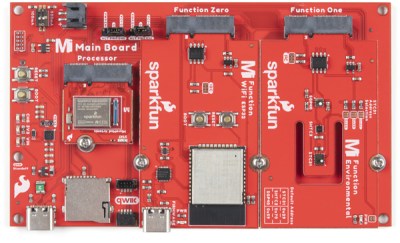
You can do a lot with a low-footprint group of 67 pins, it turns out. For instance, Sparkfun MicroMod is a microcontroller ecosystem that makes use of M.2 hardware with a custom pinout – in MicroMod’s case, it’s E-key hardware, with custom card length and the retention screw location being shifted so that WiFi cards can’t be plugged in. For hobbyists, they’re a neat and funky ecosystem with tons of different CPUs and sensors to play with – in business speak, they let us evaluate a variety of different processors for our applications. In fact, last year’s Remoticon badge spin by [Thomas Flummer] was designed for MicroMod CPUs, and just recently, [tzarc] on Hackaday Discord told us they had plenty of fun building a MicroMod-based keyboard!
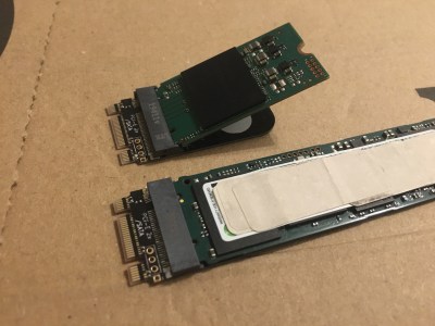
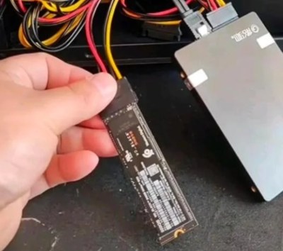
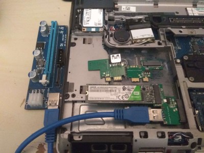
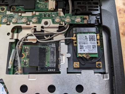 My own work with M.2 is mainly about improving laptops and bringing new life into old hardware. For instance, I’ve built quite a few adapters for reviving old laptops – i.e. small-footprint mPCIe to M.2 M-key NVMe adapters, which me and my friends use to put fast and cheap NVMe SSDs into old but still usable machines. I’ve also built a trove of M.2 key-to-key adapters for my friends’ usecases, such as one that lets you replace an A/E WiFi card with a M-key SSD, or vice-versa, and an adapter for Apple Xserve boards to use M.2 SATA SSDs in its proprietary SATA boot drive connector.
There’s a lot of fun to be had with M.2 sockets. Now – how?
Mechanical Mandates
What does it take for you to add a M.2 socket? Mechanically, its footprint, as well as some free board space. Let’s talk about board space first. Of course, you can make the card hang off your PCB – transferring the problem from the “PCB space” to the “space inside your case” area, but you still need to account for size. M.2 card size is described with four digits in WWHH format, which are width and height in millimeters – a 3042 WWAN card is 30mm wide and 42mm tall (including the card edge), and a 2280 SSD is 22mm wide and 80mm tall. When putting a footprint on a PCB, the exact location of the card edge related to the footprint will either be explicitly shown in the datasheet, or can be inferred from the cross-section image.
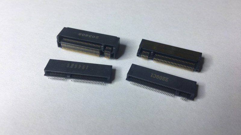
 There’s various M.2 sockets you can get – I separate them into mid-mount, flat and angled insertion, and their most important difference is the height above your PCB. M.2 socket PCB-to-card distances are actually standardized, but mid-mount and flat-mounted sockets are a less-than-standardized area – nevertheless, they’re extremely useful for making your projects small and thin. I’m a big fan of using flat sockets because they just hold your card in place, no standoff required – that said, they likely won’t work well with double-sided cards like some fancier SSDs, and I wouldn’t dare put components under the card either.
Most of the M.2 sockets, regardless of the height, use the same exact PCB footprint, since it’s standardized as well – save for mid-mount sockets, which are very useful when you need to save vertical space, but their footprints vary quite a bit more. This footprint is actually standardized in the spec and will be the same for overwhelming majority of the sockets you encounter. A friend has recently shown to me, however, that this isn’t always the case – LOTES APCI0162 is an example of an angled insertion connector that has lower distance between pads than the usual footprint sockets do. So, do recheck the footprint when buying a new part, just in case!
Acquisition And Attachment
Proper places like Digikey and Mouser will have M.2 connectors nicely sorted by key, height and mounting type. In case you, like me, choose price over convenience by shopping at LCSC, about a month ago I’ve compiled a small database of then-in-stock M.2 sockets on LCSC, since LCSC is so bad at actually keeping track of the important parameters. There’s even some G-key sockets in case your contraptions are too wacky to fit the in-spec pinouts!
I couldn’t find M.2 socket footprints in KiCad standard library – if you don’t mind borrowing footprints, I have some for you to reuse. Here’s footprints for M, B and E-key sockets, and here’s an “all M.2 socket pads” footprint – if you need a G-key or some other socket footprint, take this one and remove the pins you don’t need. This is, again, the standardized footprint that most angled-insertion and flat sockets will fit, but do check if your specific one does.
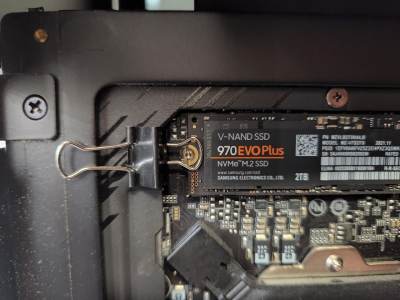
With angled insertion cards, you’ll want a standoff – otherwise, it’s not likely that the card will mechanically connect until you hold it down properly. M2 hardware will work best, and M2.5 will work in a pinch. If the card will be fastened into your case, you’ll probably grab some threaded inserts and be done with it. If you need to fasten your SSD to your PCB, however, you’ll want solderable standoffs – and when shopping at LCSC, s-ol on Twitter reminds us that we can find them using the keyword “smtso”.
What about assembly? My experience is that you’ll absolutely want a stencil with solder paste, as these are pretty dense 0.5 mm pitch parts, and a hot air gun/hotplate/reflow oven will work best. That said, with a thin enough tip and maybe preheating, you can stencil your board and then use a soldering iron in a pinch, too, or perhaps thin solder with thin iron tip – but it will be tiresome if you want to assemble more than two or three boards.
After soldering, you might still end up with solder bridges between pins – in my experience, you can clear these bridges beautifully by heating the bridge area through a narrow hot air gun nozzle from below, adding flux after the bridge’s melted and then using sharp tweezers or a needle to mechanically separate the pins. If the short joins right after separation because you stenciled too much solder paste on the pads, using good old solder wick beforehand should help too.
Electrical Essentials
For PCIe, I recommend you use M-key for SSDs, B-key for WWAN-compatible cards and E-key for WiFi-compatible slots. These three slots can handle up to 4x, 2x and 1x wide PCIe links respectively, but even if you only have 1x PCIe on your CPU, you can use either of these three, only connecting the first lane pins – read our PCIe hacking article if you’d like to know more. If SATA is what you want instead, it’s also pretty simple, just two diffpairs. At that, you can use either B-key or M-key, since overwhelming majority of SATA SSDs are B+M – here’s a board where I used M-key for SATA, simply because by that point I stocked up on some nice M-key sockets.
Where do you get pinouts and symbols from? For a start, there’s symbols in KiCad standard library, at least, in KiCad 6. Other than that, you can, yet again, get symbols from my repo – I got some for M-key, B-key, B+M key, A+E key and E-key; these work with both sockets and cards, as the footprints for cards will just ignore lack of the mounting pads that are present on the sockets. If those are limiting and you need more specific ones, there’s always the dodgy websites, and the specification floating around that I mentioned in the end of the last article.
M.2 cards will only require 3.3 V, but they might use up quite a bit of current. If you’re building custom cards, that won’t be an issue, since you know how much your device might consume. When reusing existing SSDs, WiFi and WWAN cards in your designs, however, things might get a bit more complex. Learning from laptop schematics is the simplest way – to sum it up, providing 1 A – 2 A for WiFi cards and 1 A – 3 A for WWAN and SSD cards is likely a good idea. Also, the M.2 specification mentions some WWAN cards may be built for input voltage in single-cell LiIon range (3 V-4.2 V) instead of 3.3 V. You likely won’t encounter such cards and it’s likely to be written on the label or first page of the datasheet, but this is good to know about nevertheless.
PCIe cards require PERST, CLKREQ and PEWAKE signals. That said, CLKREQ is used for gating the clock for power management purposes, and can be tied to GND on the PCIe host side – as a testament to that, the ever-abundant USB 3-cable-abusing PCIe 1x risers only forward PEWAKE and PERST. For W_DISABLE signals on WWAN and WiFi cards, you might want to add pullups to VCC – I believe they’re active low, but please do double-check. DAA/DSS signal on SATA and NVMe is a nice ‘drive activity’ open-drain signal that you can use to drive a LED. SUSCLK is a 32 kHz clock useful for card power-saving but not required in practice, and DEVSLP is a SATA-only low-power mode signal. I2C signals likely won’t be useful, but it won’t hurt if you connect them to your target – through 0R resistors, just in case.
Nifty Niceties
Building a higher-current card, or card+host combination? Technically, M.2 connectors are rated at 0.5 A per pin, so, M-key with its nine 3.3 V pins would result in 4.5 A max – that said, the recommendation for M-key is to not exceed 2.5 A, and that’s what you’ll want to adhere to. In case both sides of the equation are under your control and you’re creating your own pinout (preferably, using something like G-key), go wild and make use of as many pins with as many different voltages as you want. I just wish that Sipeed knew that when designing LicheeRV – apparently, they only use one M.2 socket pin for feeding 5 V into the baseboard. I don’t know if it’s an actual problem, but it looks suboptimal for sure!
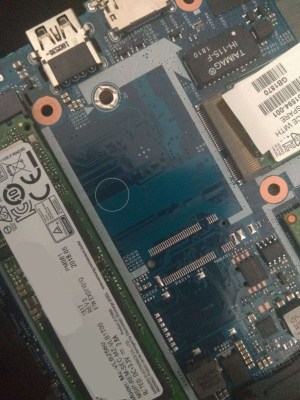 Facing an unjustifiably non-populated M.2 socket on your laptop’s mainboard? Finding a receptacle won’t be the hard part, what’s with footprints being standardized – especially if you have the schematics, as those often list the connector part number. Soldering the connector on would be trickier, however, as you can’t exactly stencil it on a populated mainboard. I recommend you wick off the factory-applied solder first so that the connector can sit flush to the PCB, then put the connector on, and use a thin tip soldering iron with thin solder to attach pads one-by-one. From there, it might be that some power management parts and signal passives, say, capacitors will be unpopulated. A good value for PCIe or SATA series capacitors is about 220nF; USB signals and stuff like PEWAKE/CLKREQ/PERST can be jumpered with something like 0R or 22 R, power management can typically just be jumpered to 3.3 V, and many other signals you’ll find to be optional.
Now, you’re well-equipped to build and hack M.2-accepting stuff, and know quite a few places where it’s useful. Next time, I want to show you how to build M.2 cards – there’s a trove of cool applications for these as well!


This is awesome – especially the LCSC links and hints – rally saved me a lot of time
Dear Arya,
So I really appreciate the article… But just don’t know if I am ‘out of date’ here or what, but for one, I thought the PCIe standard was kind of ‘super NDA’, or you are not going to get access to it unless you license it. Perhaps this has changed since. The second question would be, so ‘okay’, lets say I now have an M.2 design/card… How on Earth do I write drivers for it (PC/Linux, pull it up to the OS, so to speak ?).
in terms of building stuff, this is nothing like HDMI – afaiu you won’t need certification in order to sell a product that uses PCIe or buy PCIe-supporting IC samples, and a ton of materials for implementing PCIe connections are openly available online. Most ICs that talk PCIe, will already have the drivers taken care of, so if you’re using some off-the-shelf IC like a USB3 controller/PCIe switch/thousands of other things, or connecting to a NVMe SSD, you won’t need to worry about drivers for that.
Now, there’s, obv, the possibility that you’re doing an FPGA project where it’s a PCIe peripheral with custom behaviour. On Linux, there’s a ton of drivers available in the kernel, and writing your own is relatively easy – what’s with everything being open-source, tons of examples available, lack of backwards compat cruft and all. On Windows, if the driver doesn’t already autoinstall because the device’s standardized, like tons of PCIe devices out there, you find a product that uses the same PCIe-connected IC and install a driver for that; writing drivers (esp in a portable way), I imagine to be troublesome, because of the driver signing enforcement. That said, if you control the device end of the deal, which is the most likely reason to ask about drivers (again, FPGA-based PCIe-connected peripheral that you control), it’s possible you could implement your PCIe-facing interface in a way compatible with an already present driver, not unlike this RP2040 that emulates a NE2000 card over ISA to be compatible with old OSes.
A few pandemics back, I refurbished a Dell E7440, equipped with a M series SSD. Strangely, it was kitted out with a cable to the Mobo, plugged into a standard SSD slot. Removing the cable, and plugging in a standard SSD, (Clearly I didn’t test data speed) it allowed me to install an OS, and it has functioned for the last few years. (I’m on it now) I’m not sure how this works, (Nor do I care), but it’s a bit of trivia for the peeps.
Very cool writeup. I’m liking this series. I have one note though, regarding soldering. Check out Dave Jones (eevblog) tutorial on drag soldering I think it is called. Now I have not tried it on a m.2 connector, but the finest pitch components, at least ones with legs on the outside, are best hand soldered using a relatively fat chisel tip or even on of those concave bevel tips that allow you to store a solder blob on the tip but keep it flat. Then you do a relatively fast drag down the pins and usually if done right you get a whole row of properly soldered leads. Sometimes it takes either another swipe or two with no solder on the tip to remove some excess or if desperate use a small length of wick heated and swiped down the leg moving parallel to it. Way way way faster and even easier
For attachment to the PCB forget soldering. Just use a threaded adapter and screws on both ends.
I wish the Lenovo Tiny push pin style was more popular, those are great.
I need to get on making a proper 3d printable size adapter because the 2230 NVMe are so cheap, but not very compatible. I remixed an adapter, but it is still not very strong mechanically because it is weak in the direction of force. And no provision for a screw. Also should be minimalized for quick printing.
I remain amazed a cheap aluminum length adapter isn’t available, only overpriced and nearly useless PCB versions.
“using two M.2 B-key connectors with a completely custom pinout.” That’s what the Tamales Creek Thunderbolt module http://www.adaptertek.com/custom_88241.html is doing, too.
oh, damn, that’s peculiar! thank you for sharing!
Hi, thanks for sharing this, however i’m not able to open the link. Can you please check the sent link?
I have now maded little mod for dell XPS 9360.
Because i want to use docking station and i hate unstable thick thunderbolt cable docking station…i have soldered directly to pcie lines intel wigig card 18260. Now i can use wireless docking station from Dell/HP/Lenovo etc.
Not working is only display port because xps have missing DP lines on mainboard. All other is working – USB, LAN, audio output.
Intel wireless/wigig card 18260 needs for work fully connected NGFF (A) slot, but only some laptops have it.
If laptop dont have fully connected NGFF with two pcie lines, then is 18260 detected only as intel 8260 – only as wifi.
My first idea was to wire missing pcie ways to ngff…but wires will be too long and thats will be not good.
I have found in schematics, that my mainboard uses one pcie line for card reader IC (RTS5242).
SD slot was desoldered, SD driver IC was desoldered too and wigig card was wired directly. Now all is working fine :)
…needed pins are green marked
https://forums.lenovo.com/uploads/topic/202305/rYFnL8muN9SjVJfLmmG4ew.png?aid=AOPbKXS9KOA