With surface-mount components quickly becoming the norm, even for homebrew hardware, the resistor color-code can sometimes feel a bit old-hat. However, anybody who has ever tried to identify a random through-hole resistor from a pile of assorted values will know that it’s still a handy skill to have up your sleeve. With this in mind, [j] decided to super-size the color-code with “The Great Resistor”.
At the heart of the project is an Arduino Nano clone and a potential divider that measures the resistance of the test resistor against a known fixed value. Using the 16-bit ADC, the range of measurable values is theoretically 0 Ω to 15 MΩ, but there are some remaining issues with electrical noise that currently limit the practical range to between 100 Ω and 2 MΩ.
[j] is measuring the supply voltage to help counteract the noise, but intends to move to an oversampling/averaging method to improve the results in the next iteration.
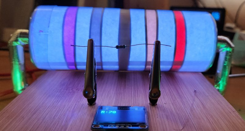
The measured value is shown on the OLED display at the front, and in resistor color-code on an enormous symbolic resistor lit by WS2812 RGB LEDs behind.
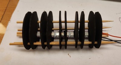
Precision aside, the project looks very impressive and we like the way the giant resistor has been constructed. It would look great at a science show or a demonstration. We’re sure that the noise issues can be ironed out, and we’d encourage any readers with experience in this area to offer [j] some tips in the comments below. There’s a video after the break of The Great Resistor being put through its paces!
If you want to know more about the history of the resistor color code bands, then we have you covered. Alternatively, how about reading the color code directly with computer vision?


Ooooooooohmmm…….
“It’s the Great Resistor, Charlie Brown!”
……..meter
Color codes should die
Why? The color code was very useful in quickly identifying a resistor’s value. It’s simple, and straight forward. But you have to make a little room in your brain to remember this stuff.
Can’t speak for TG, but personally I’m one of the fairly large number of people who are red/green colorblind. Reading color codes isn’t simple or easy, it’s impossible.
Umm I am that color blind also but never had an issue reading RETMA colors
Same here, I need a tester, I cant read the codes reliably
I’m colorblind and they can just print numbers on them now
“With surface-mount components quickly becoming the norm” LOL, where you been the last 10 years.
Surface mound can have color codes too.
Nice! I hope that it is easier to tell brown from orange if you look at it in person. This is the main problem for this kind of projects. If it works, it’s time to make a nerd clock out of it.
The background white light should help as reference for identifying the colors. I had the same idea, but I never tested it. By the way, the last band is useless.
https://hackaday.com/2021/07/15/a-perfect-clock-for-any-hackers-ohm/
Yes, I was exactly thinking of that one. As the author says: “Unfortunately the RGB LEDs cannot show a full range of colors. Brown is a problematic color along with gray and black. This tends to spoil the overall effect.”
I expect the bright background somehow helps identify the colors
I agree… Brown light is a challenge with RGB…
Brown could be achieved by using a separate white light in the same space covered by a brown colored photo film.
This isn’t a perfect solution either, but probably better than just trying to use the neopixel alone.
If you can find brown light in the spectrum I’ll give you a lollipop.
When I was going to DeVry a teacher came to each student with about 5 resistors in hand and you had to give them the correct value for each. The teacher came to my desk and I pulled the VOM out of my briefcase and started measuring them. The teacher says “You have to read the color code.” My response “I’m red/green/brown color blind and that ain’t going to happen.” Teachers response “Your in the wrong field.” My response “No, I get the resistor right every single time!” Teachers response “How do you tell wires apart?” My response “wires are bigger than resistors and I can usually tell the color of wires and when I can’t I ping the wires out. Only the red/green/brown are confusing and thats usually if they are dirty or are a wierd color.” About a year ago I was installing a snow plow on a truck and the instructions were “Orange wire goes to brake pedal for third brake light on salt spreader.” Under the dashboard I could not find an orange wire. I called my buddy over and asked which wire was orange. Under the light of my LED flashlight the wire looked white to me. He pointed it out and I cut part of it off and brought it home to show my wife. I shined my flashlight on it and ask what color it is. The wife responds “It’s kind of a real light peach color.” Yeahhhh thats not orange. Yep SMT is easier to read but harder to place for my older hands/eyes.
Boston Black
Bruins Brown
Recked Red
Our Orange
Young Yellow
Goalie Green
But Blue
Victory Violet
Gave Grey
Way White
That’s not the one I learned.
We have to be politically-correct now.
Bad
Beer
Rots
Our
Young
Guts
But
Vodka
Goes
Well
Does violet give willingly for gold silver or none?
why not just display numbers or the value?? If you are going to hook a resistor to something aren’t you just measuring it anyway? The color codes were made for visual observation not measurement. Measurement is the only true way to get an accurate representation of resistance.
Black could be represented by a ring with no light by the way. Brown could be the same ring with just a dim light or a dim red. Really the bad part of this is the silver and white and gray. White is easy enough but you can’t mix another color with white to get silver thereby leaving the gray is the only other color you cannot represent. I say it’s just a good night light!
To me something very useful would be a probe that can start at the beginning of the circuit and list the values for all the resistors along the path of the circuit as the voltage would encounter them. Could also be done for Gates diodes and the like. But I think that capability would have to be built into each resistor or other component, for it to actually happen.
Think of this project as a resistor band amplifier.
Bigger.
Bolder.
Not easier.
Awesome project and fun too. Only starts needing to read resister values later in life and about first thing I bought was a cheap LCR meter. Wonderful investment.
And good for sorting those bargain bin transistors too!
Is “embiggens’ even a cromulent word?
Perfectly cromulent in this context