If you were around for the early days of the personal computer revolution, you’ll no doubt recall the excitement every time IBM announced a new version of its beige boxes. For a lot of us, the excitement was purely vicarious, for despite the “personal” moniker, mere mortals could rarely afford a branded IBM machine. But it was still cool to keep track of the latest releases, and dream of the days when cheap clones would make it possible to play.
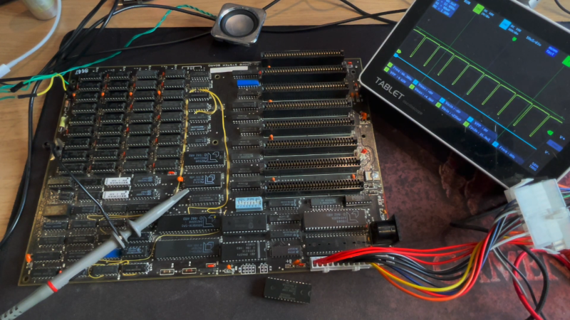
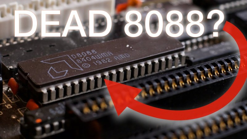
[Anders Nielsen]’s recent find of an original IBM Model 5160 motherboard sort of echoes that long-ago excitement, but in a different way. This board, from a PC XT built in 1984, was in unknown condition upon arrival, so [Anders] set about a careful process to try to bring the board back to life. A quick visual inspection leaves one with a sense of both how much things have changed, and how much they’ve stayed the same. Aside from the big 40-pin DIP 8088 CPU and the BIOS ROMs, the board is almost completely populated with discrete logic chips, but at the same time, the basic footprint of a motherboard has changed very little.
The bring-up process in the video below includes checks of all the power rails for shorts, which ended up being a good call — drat those tantalums. After fixing that issue, [Anders] had a bit of trouble getting the board to POST, and eventually resorted to dumping the BIOS ROMs and inspecting the contents. One of the chips had picked up a case of the scramblies at some point, which was easy enough to fix thanks to images of the 5160 ROMs available online. We thought the trick of using a 64k ROM and just writing the BIOS image twice was pretty clever.
In the end, the board came up, although without video or keyboard — that’s for another day. Can’t find your own PC XT motherboard to play with? Then maybe you can just build one.


Thanks for the mention!
I already got a VGA card in the mail and I have an idea for an active PS/2 -> XT keyboard adapter, so it shouldn’t be too long with the next video.
I’m sure you have came across it, the at2xt adapter uses a PIC12F629 ($5? on ebay when i grabbed one) that can easily be programmed. it drives ps2 keyboard without much issue. Long pressing alt to serial boot xtide is a little problematic, extra key presses were required to get response back. I have this chip/adapter on a micro xi8088.
Yup – did come across it. AT2XT doesn’t look attractive since, afaik, it’s closed source and I think I found an open ATTiny85 version somewhere… (googles again again … finds something completely different that does the same thing)
This looks like it works: https://github.com/nazmifr/TinyXT
Something that can be cobbled together with a random MCU(instead of a specific PIC) certainly wins if I’m going for some educational value :)
AT2XT is open source. https://forum.vcfed.org/index.php?threads/at2xt-keyboard-converter.26861/
Nope – it’s 404.
@Anders Nielsen Register and go to page 4.
I thought the same thing but the convenience of using something that is pretty well tested/matured sold me on aquiring a pic. (also my progammer could handle it)
source files are available in assembly.
https://forum.vcfed.org/index.php?threads/at-to-xt-keyboard-converter.16050/post-304769
I looked at the arduino based sketches around as you mentione. xi was based the the pic, it seems to work well.
Ah! First link is 404 but the last post in the thread on page 29 has a working link to the source.
Still – not a likely IC for many people to have compared to literally any Arduino compatible IC.
Also, PICs are a PITA.
Cool! I love to see ancient things ro be restored.
In this case, I’d replace the poor 8088 by a real CPU however, an V20. ;)
I mean, if we’re at replacing/fixing the EPROM, anyway.. A V20 compatible PC BIOS+V20 would make sense.
PS: Yes, it’s clever writing data twice if you have a chip that’s too big. Copy command in DOS/NT or OS/2 can be used (binary mode). COPY /B BIOS.BIN+BIOS.BIN >BIGBIOS.BIN (not sure if the pipe is needed, but you get the idea).
However, this will waste some space in the 640KB-1MB region later on, which could otherwise be used for an EMS page frame or UMB memory (via memory card).
So in addition to writing twice the content, someone could try to blend out one of the memory banks of the EPROM, which halves capacity.
To do so, the right address pin must be pulled high or low. Either by wiring it directly (not so recommended) to VCC or GND or by using a resistor to pull that pin high/down (safer). A floating pin is like it’s wired to GND, I guess, but it may pick up noise.
That being said, this are just some ideas. No warranties. You can use an EPROM programmer to check if the modified chip now behaves like a model of half the capacity.
Anyway, there’s lots of information about this topic. The C64 community uses that trick to store multiple kernals on a single EPROM. A toggle switch is then used to select the different ROM images.
Floating input pins are like little antennae. Maybe you don’t get any noise on it today, but that doesn’t mean you won’t tomorrow. So if you want to only use 32K of a 64K device, just program the lower half, and tie A15 to ground. Or you can burn an alternate 32K image into the upper half, and select between them using a SPDT switch. Fwiw you don’t typically see resistors to ground.
If you worked for IBM during the IBM PC era you probably had access to the internal PC Tools forums and software packages hosted across the company on their VM mainframes. It was so cool having access to people who had extensive knowledge of the inner workings of these PC’s and came up with so many neat hacks for them. Who would have thought that you could stuff 1mb of memory into a 5 slot 5150 with the right DOS drivers, original IBM memory cards and dip switches set correctly.