If you’re doing any serious work with microphones, you’ll typically find yourself in want of a dedicated preamp. [ojg] needed just such a thing for acoustic measurement duties, and set about working up a cheap DIY design by the name of ThatMicPre.
The design is based around the THAT1510 preamp IC, known for its good frequency response and low harmonic distortion and noise. The design is also compatible with THAT1512, SSM2019, and INA217 chips as well. [ojg] gave the design switch-controlled gain levels, providing greater accuracy than a potentiometer adjustment, and the ability to supply phantom power for mics that require it. The PCB is designed to rely on through-hole parts and common connectors for easy assembly.
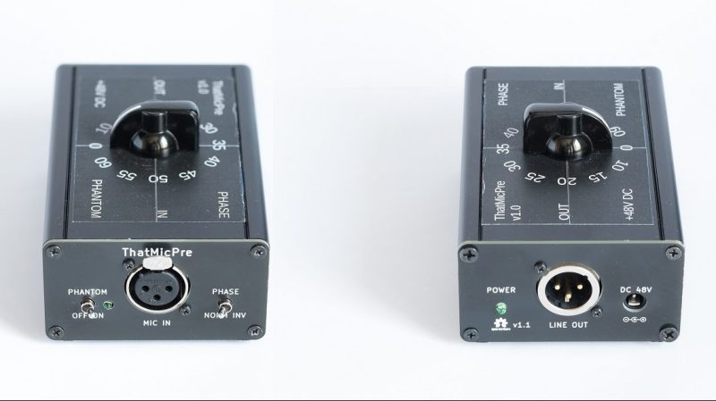
The design is open source, and has already been built by others on the DIYAudio forums. Built into a simple case, it looks like a handsome and well-built piece of audio equipment. We’ve featured quite a few unique preamps over the years, and if you’ve been building your own, we’d love to see those too!


I’d recomwnd a few changes.
The 1n4004s on the input side are pretty slow 1n4148s mat be better suited. The 2 zeners for the phantom supply are a source of noise and a 100nF and a 10nF in parallel to them could reduce noise there. The massive electrolytic used in the feedback path… Electrolytics, especially large ones can be surprisingly noisy. This may require architectural change, or perhaps just smaller caps, does the frequency response here need to go that low?
Some no polarised ones in parallel to the larger. To try quench the larger’s noise?
That´s an experienced advice !
Anybody else to chime in and constructively add to this comment ?
For me it looks like reference design from the datasheet, which also uses 1N4004’s. Also I’m not sure, but I think I see a few ceramic caps – not a good idea for this application…
One reason for having expended LF response is ripple. If you use for an example, a first order high pass filter at 40Hz, 80H,, 160Hz, 320Hz will not be totally level as filter ripple causes harmonic distortion and all filters, be them eq, loudspeakers, circuits suffer from filter ripple. Having the widest bandwidth possible equals more linear response between the extremes.
Nice implementation of a near-canonical design. Murray has offered some useful comments.
I haven’t experienced noise from modern big electrolytics, but I do like paralleling them with 0.1 uf film capacitors just in case they’re not perfect at higher frequencies.
There are no zeners in the phantom-smoothing part of the power conditioning; I suspect Murray is actually refering to the ~36v regulator. There’s a decent amount of capacitors after that stage, so I don’t know if zener noise would actually be a problem.
I wouldn’t myself use an XLR for output unless the preamp had a fully balanced out stage, for cost reasons, and so that there’s no false assumptions that it has a balanced output. Interesting choice of a 48v supply. I would be more likely to go for a bipolar supply (eg +/- 15v) and then a little voltage-multiplier to generate the phantom voltage, then some of the big electrolytics could be eliminated from the audio path.
Here’s some caveats from THAT Corp regarding input protection.
https://www.thatcorp.com/datashts/AES5335_48V_Phantom_Menace.pdf
They show 1N4148 diodes, or even Schottky diodes. in their input protection.
Indeed, the zeners are in the supply for the THAT chip, not the phantom power. Also, both supplies use a capacitance multiplier (around the transistors) and the zeners are located before that multiplier so there’s actually a ton more of capacitance after the zeners.
The output IS balanced (which simply means matched impedance, which in turn causes induced noise to be common-mode), even though it is not differential, so the use of an XLR for output is fine.
This does look well-thought-out! In particular, I’ve never seen a reproducible/selectable gain switch commercially, but wish I had one. Alas, stand-alone mic preamps seem like a somewhat neglected niche. My only design comment is more one of convenience/economy. 48V DC power supplies are rare (and not cheap). My Rolls Mini mic Preamp uses a 12V “wall wart” and derives the phantom power from that. There is likely a switching power supply inside. Never measured the noise from that. It’s probably not audiophile.
(post below was a reply to this)
Fun circuit! Re: the other comments:
– I agree that a different power supply would be easier to use, but if you don’t have issues sourcing a decently low noise 48VDC wall wart then your setup is the simplest approach.
– Electrolytic caps really aren’t an issue unless they are passing high AC current, and even then the effect is small. With such a low noise amp the mic will be by far the weakest link in the signal chain and cap distortion will never be audible.
– The diodes should be fine. If I’m reading the schematic right they are supposed to protect the input from phantom power transients, which are limited by series resistance and not super high speed anyway.
I am curious about your gain setup. Why not have the min gain setting open circuit for 0dB and the max gain resistor 10 ohms for 60dB? And why are the resistors all in series? It makes gain steps smoother if you are using a make before break switch, but layout and construction would be much nicer with parallel resistors and you probably won’t be fiddling with the gain live with a preamp like this.
Agree with Murray, nice idea yet worth some improvement. The input stage can be just reviewed, no need for 47u electrolytic, can use a smaller ceramic, this will also reduce the inrush charge when turning on the phantom power. The current limiting resistor can be of smaller power, at 10 ohm or so their noise is negligible anyway, the protection diodes should not be of such power class, rather faster and as low as possible capacitance.
But I think there is no issue with noise by zener diodes, with such capacitance around, just add low ESR smaller caps in parallel.
I support having an external 48 V PS because adding a step up converter in the same box would likely introduce noise, unless very very carefully implemented.
All possible improvements in place, a useful piece of hardware which would cost a little fortune if purchased ready – made.
No-compromise mic preamps, including ones with stepped gain, have been around for quite a while – eg http://www.johnhardyco.com/M-2details.html – of course at no-compromise prices.
Now we have some amazing specialized ICs (as mentioned: THAT1512, SSM2019, INA217) that are capable of near-ideal performance with a low parts-count and an astoundingly low price per channel… but they still require careful parts selection and construction to maximize their performance, as [ojg] has.
where do i buy one? so preferred one or two 9v batteries to stay portable. Some?