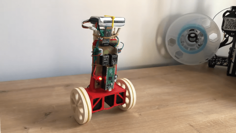
Stabilizing an inverted pendulum is a classic problem in control theory, and if you’ve ever taken a control systems class you might remember seeing pages full of differential equations and bode diagrams just to describe its basic operation. Although this might make such a system seem terribly complicated, actually implementing all of that theory doesn’t have to be difficult at all, as [Limenitis Reducta] demonstrates in his latest project. All you need is a 3D printer, some basic electronic skills and knowledge of Python.
The components needed are a body, two wheels, motors to drive those wheels and some electronics. [Limenitis] demonstrates the design process in the video below (in Turkish, with English subtitles available) in which he draws the entire system in Fusion 360 and then proceeds to manufacture it. The body and wheels are 3D-printed, with rubber bands providing some traction to the wheels which would otherwise have difficulty on slippery surfaces.

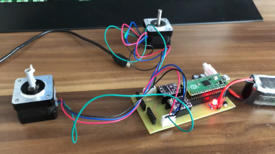
Two stepper motors drive the wheels, controlled by a DRV8825 motor driver, while an MPU-9250 accelerometer and gyroscope unit measures the angle and acceleration of the system. The loop is closed by a Raspberry Pi Pico that implements a PID controller: another control theory classic, in which the proportional, integral and derivative parameters are tuned to adapt the control loop to the physical system in question. External inputs can be provided through a Bluetooth connection, which makes it possible to control the robot from a PC or smartphone and guide it around your living room.
All design files and software are available on [Limenitis]’s GitHub page, and make for an excellent starting point if you want to put some of that control theory into practice. Self-balancing robots are a favourite among robotics hackers, so there’s no shortage of examples if you need some more inspiration before making your own: you can build them from off-the-shelf parts, from bits of wood, or even from a solderless breadboard.


When the tank on top gets empty the balance behavior has to change? How do they do it? With lower voltage the PID gets a different value ? Just kidding… nice project. But do batteries change their weight when they get empty ? :P
do batteries change their weight when they get empty ?
Yes, they do. This one stores about 50 kJ, so will gain about 0.6 nanograms mass when full charged.
That steppermotor diagram @01:52 is horribly distorted and I was wondering how that would ever work with a bipolar motor. At the end of the video ( @16:05 ) you can see two pretty much standardized (Stepstick?) stepper motor drivers.
Apart from that the video looks quite good.
Now next step a double pendulum and then a “triple pendulum on a cart” ?
Wish to have a wheelchair like this
These are available, both commercial and as diy projects.
The inverted pendulum is one of the typical cases where a fuzzy logic controller should outperform the more common PID controller.
Might be interesting to see a comparison of the two for this device.
How is this news? We literally did this during a Control Theory University Course
Was every single person in the world in that class with you? If not, then it is probably novel and interesting information to some people…