Every once in a while we stumble across something so simple yet so clever that we just have to call it out. This custom linear Hall effect sensor is a perfect example of this.
By way of backstory, [Nixieguy], aka [The Electronic Mercenary], offers up a relatable tale — in the market for suitable hardware to make the game Star Citizen more enjoyable, and finding the current commercial joystick offerings somewhat wanting, he decided to roll his own controllers. This resulted in the need for a linear sensor 100 mm in length, the specs for which — absolute sensing, no brushes or encoders, easily sourced parts — precluded most of the available commercial options, like linear pots. What to do?
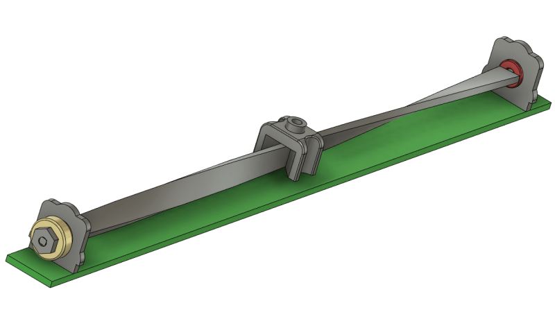
The solution [Nixieguy] settled on was to use a Hall effect sensor and a diametrally magnetized neodymium ring magnet. The magnet is rotated through 180 degrees by a twisted aluminum bar, which is supported in a frame by bearings. A low-friction slider with a slot captures the bar; moving the slider along the length of the control rotates the bar, which rotates the magnet, which allows the Hall sensor to measure the angle of the magnetic field. Genius!
The parts for the prototype sensor are all made from 0.8-mm aluminum sheet stock and bent to shape. The video below shows the action better than words can describe it, and judging by the oscilloscope trace, the output of the sensor is pretty smooth. There’s clearly a long way to go to tighten things up, but the basic mechanism looks like a clear win to us.
Hats off to [Nixieguy] for this one, which we’ll surely be following for more developments. In the meantime, if you need to brush up on the Hall effect, [Al Williams] did a nice piece on that a while back.


Very nice! And by adding more twists to it you can even get better resolution.
Only up to a full turn, beyond that it is not an absolute sensor anymore.
Nicely built but it looks like it would be quite hard to do this without backlash. An alternative method would be to use a piece of string, wrap it twice around a 32mm disk with a knot in the middle so it can never slip.
Only up to HALF a turn with one sensor (hence why I’m only using 170º of rotation, to give a nice gap)
Can you explain that?
The Hall sensors I know such as for example the AS5600 can measure over a full resolution, and I was wondering why yo only twisted the strip for half a turn. There are also many different Hall sensor IC’s and some have an analog output that is programmable, So you once set a top and a bottom, and then it interpolates liniairly between those values.
Maybe you have your sensor configured for a triangle output instead of a saw tooth?
Because I want the sensor to be cheap and simple, so I’m using a simple A1302 sensor at the bottom of the ring, instead of a more complex sensor. It’s plenty good for the throttle controller it’s intended for AND, I am not sure how a thin strip would react with a full turn, it may deform too much.
The desire is for absolute position without a homing sequence. If you use one full revolution on the AS5600, then you couldn’t tell the difference between the top and the bottom since they would be exactly the same. Maybe 85-90% of a full turn would be a good target. It would net higher resolution without the ambiguity.
what about a 10 turn pot?
Much larger than the body, and sourcing those in high quality becomes expensive and undependable. anything requiring such precision, should use a different system.
But it could also be used with small cheap trimpots to make long linear slides that are still compact. Not durable, mind you, but definitely cheaper than any linear pot of the same size.
Wheels with some preload on both sides of the aluminum bar would probably be enough to prevent backlash, though
You do realize the slider is only 8mm wide and 7mm tall, right? There is not THAT much room to work with.
You do realize the slider is 8mm wide and 7mm tall, right?
Ya off by a magnitude in one dimension there, sparky. Given the username, there’s a dim bulb joke in there somewhere…
Reads much like “Bob” is hoist by his own petard…
Really?
“There’s clearly a long way to go to tighten things up”
What did I miss?
Fits and tolerances. Each millimeter is only 1.7 degrees. If the strip is 15 mm wide, then a gap of just 0.2 mm at the edge causes the mechanism to have +-1mm of slop along the slider. One paper width causes 2 millimeters of play.
The mechanism can be made slop free, especially with the teflon sliding surfaces.
The accuracy of the measurement is directly related to the curve of the metal. If it’s a uniform curve, then it’s not a problem, but sounds like this is just twisted with some pliers. But maybe if there was an initial calibration, then it might be ok. If it changes shape during use, then it will throw off the measurement. And I’d worry a bit about wear or bending over it’s life. Maybe there could be an easy recalibration perhaps even built-in. Put a motor on the end for some force feedback, and you’d get a free calibration too.
Out of curiosity, I may just pick up a normal carbon linear potentiometer and hook both up to the scope (and mechanically) and see how linear the twisted one is. Will get back at you once I do (the pot will take a while to arrive)
You’re probably already aware of this, but pots will become noisy over time. Your hall effect sensor really is the best way to go, long term.
I have some old philips faders from the middle sixties working like this. They were used in a fixed installed modulair pa system, using regular potentiometers. Fun us: changing from log to lin is just a potentiometer away
If you start from a piece of uniform material then “just twisting with some pliers” is enough to make uniform results. There’s really no other way to do it but grab the ends and turn – under tension so the material doesn’t buckle.
Thanks, some people just overthink it.
That looks like my desk. I have no trouble clearing a space the size of a postcard in which to work.
(No comment)
B^)
I have no shame on my cluttered desk. XDDD
It would use up space :)
LMFAO, you got me.
I thought it was _my_ desk, but that’s not my ‘scope. Dead giveaway. Try harder next time. :)
Judging from the Rigol scope it is my desk :-) But the type and position of the PSU is wrong :-)
Brilliant.
Thanks! You are the only one that thinks so.
I’ll second his comment. It beats the hell out of cobbling together a rack & pinion system together and takes up a lot less space vertically. Excellent work!
I may even swap to your design when I start working on revising the throttle interconnects on my F-15 simulator.
Hope to see your implementation somewhere!
How do you get an even twist along the length?
You do the best you can, then use the sensor itself to show the relationship between distance and angle, then adjust as necessary. In fact, you could even adjust the response in software.
A neat factory-twisted metal strip might perhaps be taken from a child’s spinning top toy, the kind that is pumped to spin it up. Also I seem to recall toy helicopters that use a helix strip.
You take a strip of aluminum, clamp it down in a vise, pull on it and twist it.
Assuming of course that the strip is dimensionally even. If it’s thicker at one end, or you dented it somewhere, it’s not going to twist right.
Don’t be anal about it. It’s a 170º twist on a 100mm strip of aluminium, it’s NOT that sensible.
I don’t know about sensible, but it is somewhat sensitive to cumulative errors. The process relies on having a uniform piece of material, so it would twist the same in the middle as from the ends. Slight kinks in the starting condition can push it out of linear.
Then again, maybe you don’t want a linear potentiometer. It’s just as easy to start with a trapezoidal shape where the twist bunches up towards one end.
The strip could be set up in a lathe, Clamp the ends in the headstock and tailstock, and leave the tailstock unlocked then power up in lowest back gear or turn the chuck by hand.
You can get a very nice strip of stainless steel about 3 or 4mm wide from a worn-out windscreen wiper blade.
Yeah, I thought about using the lathe with thougher metals when I make a definitive version. Definitely turning the head by hand, tho.
Btw, for a really precise twist, I would make a “press” with a fixed and a rotary die, through wich you force the strip (fully encased and guided). Bend is fixed with a bit of twist on the rotary die.
Definitely should try someday, out of curiosity. (no plans to need more than one good sample of this mechanism for the current project, tho).
You need to pull on the material lengthwise to make sure it doesn’t start to buckle into a “superhelix”, i.e. twisting around the twist.
I replaced someones water heater yesterday and there was a really big one up the center of the old heater.
Cool!
I have never dissasembled a water heater or a petrol gauge (wich are the examples people are giving, but it’s a nice mechanism nonetheless)
I used a cylindrical, diametric magnet mounted to a hinge pin that has been modified to turn with the door. A hall effect sensor mounted to the door frame tells me what angle the door is opened to. When I plotted output over angle, my data wasn’t exactly linear but good enough for an electric door opener. I didn’t expect it to be linear, exactly, but maybe it’s one of those things where it gets more linear the further away you get… and the more you squint.
The same principle is used on the fuel tank of my old boat.
The float moves linearly and the gauge needle rotates.
I saw a small pump with the same mechanism for the fuel gauge. Looked a little like this https://cdn.shopify.com/s/files/1/0409/5754/2562/products/5100036762_Fuel-Gauge_2000x2000.png
Those are really cool! (Never heard of them, but I have not been a good petrolhead, XD) At least I didn’t think I had invented anything particularly new, just went on doing my thing.
Polaris snowmobiles had also the same mechanism for long time.
That mechanism used to be common to a great many gasoline powered devices. Lawnmowers, motorcycles, boats. Cheaper machines did without – when it ran out, the motor quit.
I love the inventiveness but what’s wrong with a linear potentiometer like that from an audio mixer?
They are shorter than 100mm.
There are some lenghty ones, but yes. Also
they are not contactless. The carbon potentiometer will inevitably die and leave you stranded, comparatively, the wear on the spiral and slider will have much longer lifetimes.
100 mm slide pots should be available.
But ask anyone who’s had to overhaul an old crackly mixing desk why you’d want to do it with Hall effect sensors if you can. :)
This is a totally awesome mechanism. Thanks [Nixie] for sharing!
Thankyou! ^_^
The mechanism is indeed very clever!
However, a 100mm slide pot with some filtering on the software side would give smooth results and would probably outlive the user himself!
@uc filtering in the software really isn’t a good solution – just how aggressive should this filter be to actually smooth out a unpredictable and every changing level of worn/dirty contact? Probably to really filter it out all the time too aggressive to actually retain enough sensitivity on the control. For some uses good enough, but most folks will want smaller movements being reliable for a much greater sensitivity overall.
Good pots with multiple contacts and well sealed ceramic slides will work “forever” – though they will wear out in use eventually.
The main technical reason not to use a pot is that the contacts always create noise when moving, always, due to the inherent mechanical contact. The main practical reason is price. Good linear slide pots cost a lot of money.
The main downside of magnetic hall sensors is a) susceptibility to EMI, b) microphonics. They pick up hum and noise from things that create a varying magnetic field, and since they’re fairly sensitive to small changes over a large frequency range, they tend to pick up mechanical vibrations as well. It’s no good if the mixing table picks up your bass drum.
Of course, then there’s other considerations, like a Hall sensor being an active component that needs power to work, and the output is a voltage that needs to be “processed” somehow. For example, it complicates matters when you have to use that voltage to control a VCA to actually change the quantity you’re trying to control, rather than just driving the signal through a pot.
There are long ones, but quite expensive.
Audio taper pots won’t work well with control systems like this. They have a logarithmic response curve whereas a “normal” pot as a linear curve.
It’s actually somewhat rare to find an actual logarithmic pot. The cheaper ones are just approximations with two linear segments.
You can find that mechanism in probably any vacuum cleaner. Slide control for vacuum power. But instead of a hall sensor, there’s a potentiometer at the end.
Linear or audio taper? What is the emitted light drop-off over length detected by a phototransistor or photodiode from the LED light source on one end of a bare optical fiber or clear rod? Does it follow the inverse square law?
Linear. It should be possible to (within reason) make a weird shaped potentiometer by “mechanically encoding” twists on the strip. (just a fun thougt exercise).
Add a stepper to the end, and you’ve got a self-positioning slider like in mixing desks.
With half a turn, it is not backdrivable.echanically speaking, it could be made to work as a motorized fader with the same toothed belt they use, tho.
I had an FM tuner that I’d slide my finger on the sliderule cursor to accurately tune the station at the other end quickly rather than turn the many-turn knob. The Ondes Martenot 1928 comes to mind as one early example of tactile linear control that is converted to rotary as in a 180degree variable radio tuning cap. I have a massive Yamaha console full of crackle pots but the big fade sliders are silent. Linear pots? No. Actually as I recall a frictional disk on the pot and a grabby linear sliding rail sans gears and cable. Cheap but still works.
I need to hack a 10turn pot to linear motion cable pointer above a keyboard and set it to one volt per octave and patch to my Arp. It’s easy to play for any keyboardist vs. waving your hand in the air.
Here’s another way to implement this. You can use a lateral-effect photodiode. Just place that at one end of the stick’s travel. On the stick, place a small laser pointer, pointing at the LEPD, but slightly angled, so that as you move it back and forth, it points at different positions on the LEPD. Be sure to enclose the setup to prevent stray light from adding noise. By measuring the output of the LEPD, you can infer the stick position. One downside: the stick carriage needs to not have any angular slop, as that can lead to incorrect measurements. You could probably come up with a slightly different arrangement to avoid this.
That’s a totally different thing, not “another way to implement this”. This approach aims for simplicity and reliability, not complex electronics and “zero angular slop” on one part. For that matter, I would use a ToF laser rangefinder and bounce it on a slider with apropriate reflective surface. BUT that’s not what I want/need.
A lateral-effect photodiode is the same level of electronic complexity as a hall-effect sensor. One is affected by light, the other by magnetic fields. Either can be read with an analog input.
Like I said, the issue about angular slop can be resolved easily enough by a different arrangement. One possibility is mounting the LEPD off to the side of the stick’s travel, and then using a LED on the stick pointing towards the LEPD. The LED would require a lens to focus its light onto the LEPD; a pinhole “lens” would probably work fine.
Using a LEPD to detect a joystick’s position isn’t my idea. Some versions of the Microsoft Sidewinder joystick used this mechanism (with a 2D LEPD) to detect the position of a 3D joystick (2D plus twist).
This is actually how some common fuel level sensors work. The fact that you can just measure the magnetic fields (which travel through objects) makes it very easy to seal and make chemical resistant. https://www.kelch.com/products/caps-gauges-and-sensors/multi-level-gauge/
As mentioned before though, the trick with this approach is minimizing both slop and friction as they are often opposing. The fuel sensors we use have a significant amount of slop since they have to move only by the forces of buoyancy on a small float.
Nice idea. I suspect using the wheel sensor assembly from a ball mouse might be similarly effective. That would only make sense to try (instead of this) if you had a source of cheap old mice (probably free now since nobody uses them anymore) though mounting the wheel might be trickier than this as well.
No and yes.
This is an absolute encoder, that is, it always knows where it is at all times, powered or unpowered. Whereas a ball mouse wheel is an encoder, it doesn’t know where it is until you tell it so, and looses track when you remove power.
In short, it would work, but you would need to calibrate on startup and tell it “this is Zero” and it would then count up and down as you moved, and I’m too lazy to do that startup routine everytime.
you can put another bar with reverse spin, to obtain best reads, good work 👍
Simple, tried and true and nicely executed. Great job! I do like the KISS principle here. Less is more. I need something like this for a project…
You guys in the comments should chill out… Propose alternatives that might also work, sure, but “you did it wrong, here’s a solution that is complex and won’t work nearly as well” sucks. You do you, Nixie.
Thanks!
Someone that gets it!!
Thankyou ^^
I’d grab a $7 set of digital calipers and an interface for them to connect to an arduino. .001″ precision, absolutely measured from 0-6″
I recently needed a similar thing for a scissor lift mechanism and needed the absolute position of a lead screw with a movement of 200 mm in length. I used a belt and pulley to drive a multiturn potentiometer to get the resistance. This I then use to make a kind of linear servo with range of 200 mm . The sensor is actually 20mm in diameter and 30mm in height and occupies a lot of space.