It is no secret that semiconductor junctions change their behavior with temperature, and you can use this fact to make a temperature sensor. The problem is that you have to calibrate each device for any particular transistor you want to use as a sensor, even if they have the same part number. Back in 2011 1991, the famous [Jim Williams] noted that while the voltage wasn’t known, the difference between two readings at different current levels would track with temperature in a known way. He exploited this in an application note and, recently, [Stephen Woodward] used the same principle in an oscillator that can read the temperature.
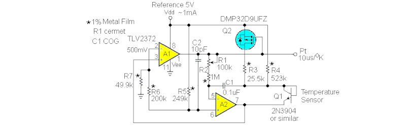
The circuit uses an integrator and a comparator. A FET switches between two values of collector current. A comparator drives the FET and also serves as the output. Rather than try to puzzle out the circuit just from the schematic, you can easily simulate it with LT Spice or Falstad. The Falstad simulator doesn’t have a way to change the temperature, but you can see it operating. The model isn’t good enough to really read a temperature, but you can see how the oscillation works
You can think of this as a temperature-to-frequency converter. It would be easy to read with, say, a microcontroller and convert the period to temperature. Every 10 microseconds is equal to a degree Kelvin. Not bad for something you don’t have to calibrate.
Thermistors are another way to measure temperature. Sometimes, you don’t need a sensor at all.


I think you mean AN45 from 1991, not 2011.
Time machine is busted.
“degree Kelvin” – I can almost see my old physics lecturer’s left eye twitching as his face turned purple. Such fun putting the degrees symbol in front of the K just to wind him up
Maybe the article is very old:
“In 1967/1968, Resolution 3 of the 13th CGPM renamed the unit increment of thermodynamic temperature “kelvin”, symbol K, replacing “degree Kelvin”, symbol °K” – https://en.wikipedia.org/wiki/Kelvin
I’ve seen it in use in some technical documentation from the 1954 to 1968. So it did exist and was used.
Yeah that’s a fairly modern thing to drop the degrees. Like condensers and capacitors ;)
Not busted. Thermal calibration error.
On June 12, 2011 James M. Williams died the author of the AN45 wich is from 1991.
for more info: EDN Dec 28, 2022
That’s one way to measure temperature.
Another way is to buy a temperature sensor IC. They are tiny, inexpensive, pretty accurate, and come in digital or analog versions.
“Just buy the IC”
Nice hack!
Don’t make your own circuits, only buy premade boards! They’re cheap enough that you’ll almost always spend more rolling your own.
All 3 levels of abstraction are perfectly acceptable for having fun and learning.
I used to service a product we made that was used for HV busbar and switchgear temperature measurements.
Two parts to it. An antenna that broadcasts at a known frequency and these resonators on a substrate with their own antenna. As the temperature goes up, the spacing between the resonators goes down, raising the frequency that was retransmitted. This change was linear so with a infrared gun, shoot the temp, set the temp in software and now you had unpowered, wireless high voltage busbar temperature monitoring. Especially useful to see if one phase is getting too hot or poor connections.
Could a BJT be simultaneously used as a gain device and its own temperature sensor? That is, would it be practically possible to estimate temperature increase by measuring the the base-emitter voltage under service conditions (as a Class A amp, for example), with signal voltage on base and varying collector current? I reckon you could write down an equation, but it might be too ill-conditioned to allow useful temperature data to be extracted?
It’s possible, but would be a fair amount of work for mediocre results.
If you hold temperature constant, collector current (Ic) is an exponential function of base-emitter voltage (Vbe). Flipping it around, Vbe is a log function of Ic.
If you hold Ic constant, Vbe is an almost-linear function of temperature[1]. For any given collector current, you can measure Vbe and plot it against temperature. Then, to a very good approximatiion, the tempco of Vbe at that Ic will follow the line between (T,Vbe.measured) to (0,1.25V).. the bandgap voltage of silicon at absolute zero. If you do that for several different values of Ic, you’ll get a fan of lines that intersect at (0,1.25V).
[1] There’s a slight curve. Circuits that ignore it are called first-order temperature circuits. Ones that apply a parabolic correction are called second-order temperature circuits.
If you measure both Vbe and Ic, you could plot points along a (T,Vbe,Ic) surface. Unfortunately the exact surface depends on the design of the transistor and is sensitive to production variations. Going just by Vbe and Ic, you’ll see maybe 30% variation between transistors from the same batch.
The Williams circuit (and all bandgap temperature circuits) solve that problem by taking advantage of the fan of lines mentioned above. For any known ratio of collector currents Ic1/Ic2, the corresponding Vbe1 and Vbe2 points live on two lines that intersect at a known location. The value Vbe1-Vbe2 is linear and Proportional To Absolute Temperature (PTAT) in a highly predictable way.
You could get an Ic1/Ic2 ratio by measuring the maximum and minimum voltage at the output of a class-A amplifier, and use that to plot expected Vbe1 and Vbe2 values to get a PTAT.
The problem is that the larger Ic1/Ic2 gets, the more distortion you get from a class-A amp. The design goals for a good amplifier produce a bad PTAT, and vice versa.
The math:
Ic1 = Is * e^( Vbe1 * q / KT1 )
Ic2 = Is * e^( Vbe1 * q / KT2 )
Ic1 / Ic2 = e^( Vbe1 * q / KT1 ) / e^( Vbe2 * q / KT2 )
ln( Ic1 / Ic2 ) = ( q/K )( Vbe1/T1 – Vbe2/T2 )
where:
Is : reverse leakage current through the PN junctions
q : the charge of an electron (about 1.6e-19 Coulomb)
K = Boltzmann’s constant of thermal energy (about 1.38e-23 Joules/Kelvin)
Is is wildly nonlinear so making it drop out of the ratio is A Good Thing.
Voltage has the units of Joules per Coulomb of charge, so K/q is about 86.25uV/K.
If T1 == T2, we can continue with:
ln( Ic1 / Ic2 ) = ( q/KT )( Vbe1 – Vbe2 )
T * ln( Ic1 / Ic2 ) = ( Vbe1 – Vbe2 ) / ( K/q )
T = ( Vbe1 – Vbe2 ) / ( 86.25uV * ln( Ic1 / Ic2 ) )
Thanks, I appreciate it! I’m in awe of the quality of your response to my vague musings! I will copy your derivation and try it out next time I have a free weekend. The signal-to-noise ratio on hackaday is astoundingly high!
What about η (eta), the “ideality factor”?
Unless you have a temperature compensated (TCXO) crystal….this won’t be as precise as you think it will be.
What’s easier to measure accurately, voltage or frequency/time? Because you could also apply two currents with a known ratio and measure ΔVbe.
I just built an extremely simple circuit to measure light, temp or similar with espo266-01, which does not have an ADC. The code is about 6 lines.
Typo: ESP-8266-01