Hobby servos are nifty and useful for a wide range of projects. There’s nothing stopping you from building your own servos though, and you can even give them nifty features like 360-degree rotation In fact, that’s exactly what [Aaed Musa] did!
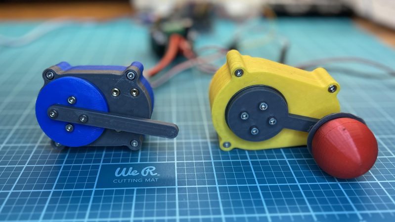
The servo relies on 3D printed gears in a 3D printed housing. The design makes prodigious use of threaded inserts to hold everything together nice and tight. A DC motor is charged with driving the assembly, as with any regular servo motor. However, in the place of a potentiometer, this design instead uses an AS5600 magnetic rotary position sensor to read the servo’s angle, via a magnet mounted in the servo’s gear. An Arduino is used to determine the servo’s current position versus the desired position, and it turns the motor accordingly with a BTS7960 motor driver.
The result is a sizeable and capable servo with an easily-customizable output, given it’s all 3D printed. If you’d rather just mod some servos instead, we’ve covered some great work in that area, too. Video after the break.


Seems to me the motor is not 3D printed. However, very cool housing and gearing.
Neither are the circuit boards, solder, wires, bearings, fastener, heat steaks or IC’s 3D printed. Nor does it appear to use a 555 timer.
Best Rick Roll ever 🤣🤣🤣🤣
Best Rick Roll ever is the Sprite_TM badge hack at Hackaday Supercon about 5 years ago.
Thumbs up 👍
My suspicion is that the torque from this is rather on the low side. Nice magnetic absolute encoding sure, but until there’s a much higher reduction gearbox it isn’t really all that useful a device.
A 600 rpm motor already has a 10:1 reduction box inside. I expect with the added ratio he’s getting about 3 kg-cm at 12v which is certainly useful for many applications. I totally agree the video would be more useful if he went briefly into some of this.
Back in the day (70s) people used to modify regular RC servos into continuous rotation and multiple rotation units, specifically for RC model yacht sail winches. You could buy these special sail winch servos from the RC system manufacturers but as you would suspect the prices of these were outrageous.
So to do this the regular servos were disassembled, the detent stop lug filed off the final gear and the feedback pot taken off the geartrain and out of the unit to be replaced in a different part of the output or with another multiturn component, or even removed entirely.
I modified a few (4 or 5) standard servos to infinite rotations as you say and by replacing the pot meter with a home brew one ,using a 3d printed bracket holding an AS5600 and a rod holding a 3mm ball magnet connectet to the output shaft.
arduino promicro as a controller and an l298 as motordriver, I use it on my reprap for the extruder, its configured to work like a steppermotor with 4096 steps each rotation , it gives a lot of torque for the weight and lost steps is history (the PID will make it catch up in case it start lagging).
Of course the Arduino and motordriver dont find place in the standard housing they are glued in a box
on the side of the servo.
B.T.W you just dont tell it to go to zero after a 10 hour print :-).
Great project! I’m finishing a project quite similar, although I only cover the electronics part, like OpenServo, but it’s called LibreServo. Any criticism would be welcome:
https://hackaday.io/projects/hacker/380334
Beautiful engineering work in action.