In an ideal smart home, the explosion of cheap WiFi and Bluetooth chips has allowed hundreds of small wireless devices to control the switches, lights, and everything else required for a “smart home” at a relatively low price. But what if you don’t want hundreds of internet-connected devices in your home polluting the wireless spectrum and allowing potential security holes into your network? If you’re like [Lucas Teske], you might reach for something wired and use cheap and (currently) available Raspberry Pi Picos to create PicoHome.
The unique twist of PicoHome is that it uses a CAN bus for communication. One of [Lucas’] goals was to make the boards easily swappable when hardware failed. This meant board-to-board communication and protocols like I2C were susceptible to noise (every time a relay triggered, the bus would lock up briefly). The CAN bus is designed to work in an electrically noisy environment.
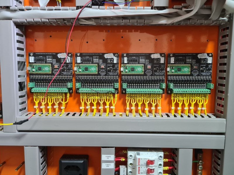
There are two parts to the system: pico-relay and pico-input. The first connects to a 16 relay board and can control 16 different 24v relays. The second has 16 optoisolators to read from 12v-24v switches and various buttons throughout the house. These can be placed in a giant metal box in a central wiring location and not worry about it.
The firmware and board files are all released under an Apache 2.0 license, but the CAN2040 library this project relies on is under GPL. We covered the CAN2040 library when it was first released, and it’s lovely to see it being used for something entirely unexpected.


Nice work done, but I am not sure if it is worth the effort.
There is a well known and long time established standard called KNX, where these kind of modules can be procured from several independent manufactures (like GIRA). All these are connected via a two wire bus.
Because the KNX standard was first established within the industrial usages, it is reliable and can cover a lot of use cases.
I implemented this within my complete house wiring. From lighting, heat control, sunshades, PIR, up to a nice visualization done with home assistant.
and there are some open source implementations out there, like freebus or selfbus.
knx is extremely reliable, i installed it back in 2004 to my home, and had 0 problems in these almost 20 years with it.
Konnex has the application layer fused with the transport layer (in the ISO model) so it makes impossible to deal with generic, not already defined messages which makes it limited in scope. To me it’s an outdated technology born just to handle the traditional household functions conceived in a world where WiFi didn’t exist. RS485 based generic protocols are far better as they may embed new unforeseen functions,best suited for the modern houses.
Looks a lot like the remote IO boards what we (at ex employer) used in the secound have of the 80s. these boards where 8051 based with a RS485 multi master communication.
Today (from 2010..) all digital Inputs and Outputs are done with industrial ethercat modules (but specs/quality is NOT what we where used to (:
In the early 90s the boards where replaced with DIN modules (boards size 100x160mm), on top 25 Din female bus, bottom 4Bit adr dipswitch and on front Inputs/Outputs/Leds. (in production till 2015)
Every unit (box) had a prosessor module, for coms, interrupt inputs and PSU. Further more there are Output, LCA, ANAlog and even a CAMera module(s) with a max of 7 modules on a single processor module.
Specs:
Power 24 V DC +/- 50 % (garanteed at worse case)
Coms: RS485 halve duplex 375 kbps 9N1 multi master (2 pairs)
Software: (property) Boot part in Eprom (16k) or flash, Appl (16k) part downloadable in Ram
Inputs: 24 V DC (Low 0..8V, High 10..40V)
Output mod: 24x 250 mA coil drive (protected agains overcurrent and ,permanent, short’s)
I/O mod: 8 In and 16 Out
Analog Mod: 8x ADC 8Bit 0..10V and 2x DAC 8Bit 0..10V plus 4 NO/NC relais outputs
Camer Mod: 5x camera coax PAL with a DSP for image processing.
That 8051/RS485 project sounds similar to the BITBUS controllers I networked together back in the day to control high mailing and packaging machinery. Intel actually had an 8044 chip which contained the 8051 with an SDLC (IIRC) controller. (The primary/master controller was actually a DOS-based PC written in… Turbo Pascal!) Good Times!
That was actual the 8033, i waited nearly a year for it together with the BITBUS specs but the didn’t came in time :( so we created our own protocol.
Is it compatible with Home Assistant?
Yes, indirectly. I still plan to make a bit more detailed how to setup, but the current software sends everything to MQTT, and you can map MQTT queues on Home Assistant ^^
I use the VSCP protocol as messaging protocol between hardware I/O nodes on top of a CAN network. It can also run over Ethernet, wifi, …
Each node can initiate connections. (Multi master.)
I’ve designed my own custom hardware for this and it was prevously integrated with MisterHouse.
There are nodes available for VSCP in NodeRED, which I use now to integrate it with HomeAssistant.
Impressive wiring and layout – except for the pair of wires dangling in front of the unit. Especially the one with a taped joint!
I wish you used a PicoW and it talked WiFi.
It’s Arduino code so there’s no reason you couldn’t target a PicoW and add wifi
Then you missed the point of the project.
Some people just like to argue
No we don’t.
Careful, I take my meds and you will disappear.
I think the main reason everyone uses wireless is because running all new wires isn’t feasible. It’s a lot easier to just reflash the firmware on bulbs/switches to get rid of the cloud.
Yes! I’d love to run cables through my house but cheap construction makes it so hard. I’d need to run a conduit on the outside on my house to get a cable run from upstairs to downstairs cleanly, and that means applying for HOA approval.
I’ve been building my home automation with $5 ESP-8266 clones running Arduino, and they are all connected via the MQTT server running on my NAS.
You are invent Loxone
Would be cool if someone did a solid state relay system that also replaces the breaker box. If it works for racing cars why shouldn’t it work for homes? You can monitor consumption, set custom current limits, reset fuses, set outputs to be on/off or dimmable etc etc.
I mean something like this but for homes:
https://www.hardwire-electronics.co.uk/product-page/pdm-25
It would be cool if someone did that at a price comparable to current power distribution equipment. You can get a 200A breaker panel and 10 20A Square D single pole breakers for under $250. The product you linked to costs nearly £1000.
I’m exceedingly happy to have a decisive physical breaker that will definitely not arc once it has broken. I don’t know if you could achieve that on silicon. You can do it in cars because there will be relatively little arcing and the voltage itself is not dangerous, although you could certainly start a fire if the breaker failed.
I think the larger issue would be that circuits in a house span multiple outlets and often multiple rooms… Lighting circuits are basically never just one room, so you’d be dimming half the house at once. If you switched off an outlet to turn off a lamp, you’d also be switching off all the outlets in the other side of that wall on the same circuit.
You could obviously just keep adding circuits so you had them separate enough to control at the breaker level, but that’s A LOT of extra copper to have to pay for and run just for that “convenience”.
I do smart home installations. Specialising in supplying ‘hidden smarts’. Often people don’t want funky touch switches, graphic displays, etc. They just want ‘normal’ switches. It’s often the case that one or more residents want smart stuff, but they live with others who don’t. Wherever possible I run every lighting circuit and every switch wire to a single (reasonably large!) junction box. That way we can connect up the system ‘traditionally’ and then add the smart switching at a later point.
I’m a big fan of the Shelly range of devices. That makes ‘hidden’ smarts really easy.
Why CAN bus exactly? There are other ones that were literally designed to work in electrically noisy environments. Like RS232 as one example. Not seeing why this is in any way better for this use.
Well, I just wanted to play with CAN and raspberry pi pico. It is used in drones and other devices and I wanted something I could broadcast from anywhere and just use a bus-like interface. RS232 for instance is not bus like.
RS232 is not a bus. It would be a nightmare to control all the devices in a smart building with RS232. CAN is designed for electrically noisy environments. It seems like a reasonable choice.
Not saying CAN is a bad option here (though each packet is more complicated and limited in what it sends and how by comparison) but you can also use RS485. Either one is hugely better than I2C for this type of use if you really need a bus instead of a direct connection.
Serial (at least with proper cables and more using RS485) is also designed for electrically noisy environments and can easily go 4,000 feet or more. Uses a balanced and differential serial connection. That’s the whole point of how it works.
Nicely done! With cheap reliable Pico Boards to boot! I like.
One of my concerns too is the ‘wire-less’ craze for house automation and all the ‘security’ concerns that go along with it (which most people seem not to care or aware) . Convenience vs. security.
Exactly my concern here. I wanted it to be 100% wired (although I have wifi and use home-assistant in mobile phones).
I too have Wifi. But I have two networks here. One for the home network, and one for access to the internet. So people with cell phones (myself included) can use our internet connection, but no access to the home network from external devices. Automation hardware only ends up on the home network, never directly connected to the internet. Limits me a bit, but I feel ‘somewhat’ more secure. Home desktops that need access to both have two RJ-45 network interfaces (motherboard, and an add-on card). Anyway, that is ‘one level’ of security.
Just as a follow up (I’m really honored to be here in Hackaday!) – There is also another board that will go into the relay boards so everything is in the same CAN bus. The code and design for that board is already available, but since I want it to run _without_ a computer, I’m still working out on how to map each input to each relay in a simple way using a computer and then persist on the boards.
Also for everyone that asked, I use home-assistant here, but I control those boards through MQTT (the inputs are forwarded to a topic INPUT/x and the outputs are managed at OUTPUT/x )
I used a Raspberry PI to change settings (timers, schedule, home/away, etc.) in a few Arduino Megas via I2C. I used an old 400W computer PSU to provide power to the RPi and Arduinos. A cheap desktop UPS keeps it running. All the “smart” stuff is mounted at the top of a closet, out of sight (because my work is ugly!)
The Megas “remember” everything and control I/O directly (through some “hats” I soldered with Darlington transistors to switch 12VDC). The 12V signal is run to relay boards mounted at the top of the wall (in the attic) via CAT5 cables, to drive the relays that switch 120VAC for the lights/fans. Same basic setup to use 12VDC through the existing wall switches to switch inputs to the Arduinos, with voltage dividers at the Arduino inputs to bring down the voltage.
Install was easy, as all you need to do is identify the incoming 120V supply, and cut the Romex at the top of the wall to make connections. CAT5 is color-coded, so terminations are easy. I used different cable colors for input and output, to avoid confusion. A small 3-gang box at the top of each wall houses terminations, and keeps it all safe.
It’s basically a centralized control, with remote I/O boards to simplify comms and negate the issues you had with I2C freezing. Most relay boards are 4 input, 4 output, as that is more than I need for my 2-switch wall plates and fits nicely in a pair of CAT5 cables with common wire being two pairs to handle load. I have one 7-channel board for the 5-switch wall plate in the living room that required a different setup, but everything else was kept identical for easy replacement.
For me, simplicity and low budget were the main considerations. Your system is much more impressive… and pretty. I imagine it’s more robust, as well.
I like your system but I can’t find in the code the way to connect to a MQTT broker.
How can I do it?
Thanks
This article reads like wired and wifi are the only choices. Z-Wave or Zigbee is the best of both worlds. You get the ease and convenience of wireless, without the security concerns of putting your setup out on the internet.
Wireless anything is a no-go for many circumstances. It’s not the best of both worlds, though certainly better than wifi.
A lightbulb should NEVER be smarter than your home! Kudos for making a pro-level system for the home!
I just wish mine looked as nice as yours.
I have a wired setup as well, with tens of modules based on Arduino Nano clones (because they are nearly free and very robust).
The PJON communication bus I use is extremely robust, and the wires can be more than a km long. It also needs no communication shield so can be driven directly from the Arduino digital pins (meaning very low cost).
I run my own protocol ModuleInterface on top of PJON for simplified synchronization of settings, inputs and outputs plus two-way sync through MQTT with Home Assistant. Check out PJON on github, or visit pjon.org.
Disclaimer: I have contributed to PJON.
Would be nice with a cheaper alternative to what i have now, whole house runs on dupline(Modbus) everything is expensive. Cheapest part is the switch to turn on the lights, $150. relays, fire alarms etc are just crazy, everytime some breaks down.
Lighting and heating systems should only be hardwired using a Can bus data system. Ethernet and WiFi control should be setup as a spy system and isolated using a gateway, this can be unplugged leaving a working system. If you are going to retrofit your house with data cabling then you should use a reputable company to supply your equipment, having good support and long term manufacturing supply.
You can buy modbus relay board on alliexpress for 30$, 2ch analog input board for modbus is like 4$. Then just slap usb modbus to your HA server and you are golden.