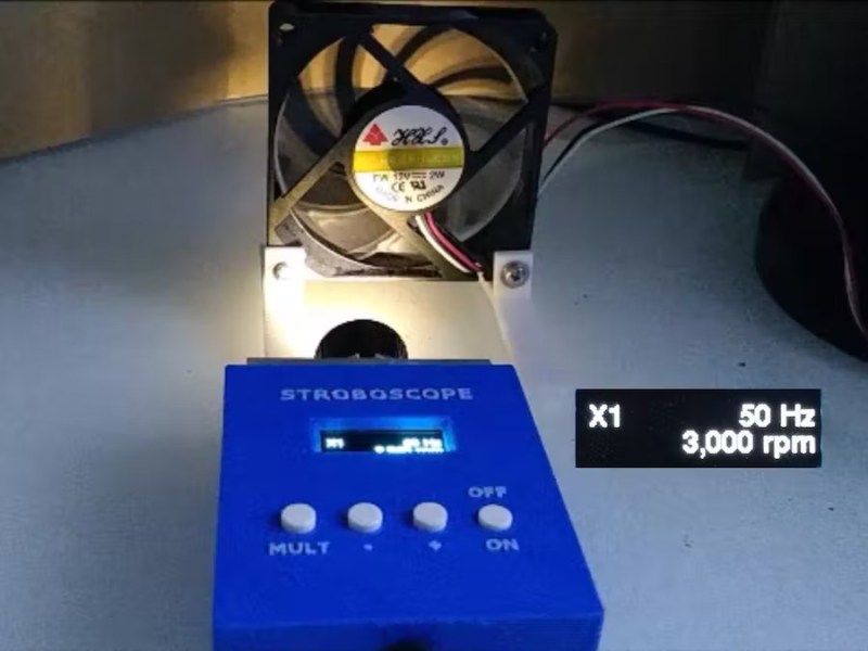
A stroboscope is not the most common tool, and while they can be purchased fairly inexpensively from various online stores, they are straightforward enough tools that plenty of us could build our own mostly from parts laying around. The basic idea is to shine a flashing light on a spinning object, and when it appears stationary the stroboscope will indicate the rotational speed. There are a few specialty parts that might not be in everyone’s parts drawers, though, and [John] shows us the ins-and-outs of his own DIY stroboscope.
The effect relies on extremely precise timing, and as such the most important part of a build like this is making sure to get the LED circuitry correct so its duty cycle and frequency can be tightly controlled. [John] is using a PT4115E driver board for the LED, and is using it to power a 1W white LED which also includes its own heat sink and lens. The controls for the stroboscope are handled by an ATtiny1614 microcontroller which shows its pulse rate on a small screen. The user can control the rate the LED flashes with simple controls, and when the spinning object appears to come to a stop the only thing left to do is read this value off of the screen.
While it might seem like an overly niche tool, stroboscopes have plenty of day-to-day uses. Older cars that used a central distributor made use of a specialty stroboscope called a timing light in order to properly advance the ignition timing of the engine. They also retain some use in medical applications, and plenty of older readers may be familiar with their use adjusting the speed on record players. They can also be used to make sure the shutter speeds on cameras are calibrated correctly.


Kinda neat that the PT4115 constant-current driver will apparently go fast enough for this to work, with its 2 us rise/fall time and minimum pulse width of 10 us (the maker uses a leisurely 200 us pulse width). And it’s good that the 0.3A peak current the circuit can provide is sufficient for the application.
It’s not obvious from the video whether the LED current modulation that the PT4115 produces is visible during the pulse.
For reference, with the duty cycle used, that LED can easily be driven at 1.5 A. A low-cost MOSFET with the correct gate drive can easily get 0.1 us rise/fall time into that load, should you ever need much better performance: It’s easy to get a microsecond photoflash this way, though the light output is a lot less than an air-gap flash, even with a 100W LED driven at 1 kW peak.
And FWIW, there’s no point going faster than 1 or 2 microseconds anyway: that’s the decay time of the phosphors in white LEDs. If you want to go faster you need to use a LED with no phosphor, but then the light output is so low to be useless for anything bigger than a marble.
I made a stroboscopic microscope illuminator several years ago that dumped a few amps into a blue or green LED. IRIC, I had the pulse duration adjustable between 5 and 100 us, and the flash rate went from 1 Hz (ouch!) to 500 Hz. It turned out that 15-25 Hz was ideal for observing cilia on microorganisms, but was hard to look at for very long.
The most interesting thing I observed was that the motion of the cilia had the same sort of waves that you see in the movement of the legs of centipedes. Single celled organisms don’t have nervous systems, so all that coordinated motion was just the result of cascading chemical reactions. Incredible!
I started with blue (short wavelength, high resolution) but switched to a green LED because 1) single wavelength (mostly) so even cheap microscope optics could provide a sharp image (no chromatic aberration), and 2) human eye sensitivity peaks in the green spectrum, so even relatively dim, short duration pulses provided acceptable visibility of the microscopic features of the organisms being observed. When I was using the blue LED I noticed that chlorophyll fluoresces red.
One reason I ditched the blue LED is because of potential harm to my vision, though probably not really comparable to being out under a blue sky every day, anyway.
I had an idea that I never got around to trying- use a different color light, say red, that is on most of the time, shutting off during the green light pulse, which should result in the moving parts being highlighted in green while the resting parts appear red. You wouldn’t see the cilia in red because the light is on most of the time and the cilia are usually moving fast. But throw in the short green pulses and you will freeze the cilia with the green light. The trick would be to run the red, mostly-on light at a brightness that matches the average brightness of the green pulses. I think this would work best with dark-field illumination.
Don’t forget applying this to illuminate your favorite 3d printed zoetrope!