If you wanted to create a VGA card, you might think about using an FPGA. But there are simpler ways to generate patterns, including an old-fashioned EPROM, as [DrMattRegan] points out in a recent video.
Generating video signals is an exercise in periodicity. After all, an old-fashioned CRT just scans at a certain horizontal frequency and refreshes the entire screen each time it starts over. VGA is made to drive this technology. An EPROM chip can easily generate repeating patterns when driven by a counter at a known frequency.
As you might expect, there were a few software glitches to work out, but in the end, the circuit did its job, displaying a fixed image on a VGA monitor.
If you haven’t run into [Matt] before, he has a complete series on how he built a “wire-by-wire” Apple II clone. We will warn you, though. Don’t click on the link unless you have some spare time. The 18 videos take over two hours to work through, but there is some beautiful prototyping and a lot of good information in them.
You can go even lower tech for a VGA card, if you like. Just try not to look like this breadboard.
Thanks [Stephen Walters] for the tip.


will put this on my viewing list – thanks.
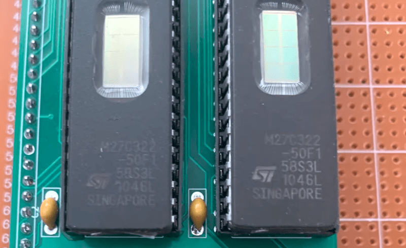
Never seen EEPROMs *that* huge !
Did you mean physical size or capacity?
EPROM. 27C322 need UVC light to erase them.
FPGA is only associated with VGA because its a wonderfully apt example of data in a given format and data out.
Forgeg the VGA, look through the EPROM window!!
An enjoyable presentation!
Reminds me of the “World’s worst video card” https://eater.net/vga
I’ve wanted to do a project using parallel EEPROM or flash as a LUT before. I believe the primary constraint is that access times can be pretty long.
Is there some clever reason that will be revealed in the next episode as to why he put the adress of the next pixel into the EPROM memory?
Just spitballing here, but swapping out a couple of those buffer chips for a counter that generates the address and using one bit in the pixels as reset for the counter seems like a more obvious design to me.
One less EPROM chip needed, and you can use a smaller one at that.
When you have a hammer, everything’s a nail.
Thanks to everyone who has watched the video.
Yep, it can certainly be done with counters (which i did in part 8 of the apple 2 wire by wire series). The trick is that i (eventually) want the raster count to be tri-state for half the clock cycle.
I’ll spill the beans here though, i have a 6502 design that takes about 10-15 chips, two of them are these EPROMs (27C322). It can also run Z80 machine code (with an extra EPROM). The shortest series on this is here (https://www.youtube.com/watch?v=mPkAgXJOoSc&list=PLjQDRjQfW-84aOLT33kzoZghRofK-uL1F)
I have some spare capacity in the EPROMs, and it’s not used while clock is high, so i want to fit the raster generator into the same EPROMs that forms the CPU. No counters needed at all, just a few octal D-type flip-flops on top of the current design.
This was a dry run for the prototype before integrating it into a CPU. Storing the image in the same EPROM(s) was just to test it, i’m after the raster pattern.
Enjoy.
There once was someone who made an image sensor out of an eprom.
Loaded all zeros or all ones to the eprom and then focused an image onto the array.
It was only black and white and had impractical long exposure times but it did work.
Unfortunately I cannot find the link anymore.
Done that years ago with a cheap AVR controller, generating a custom startup logo generator on the cheap. the image was in flash and a small assembly program would get the byte and output it on the ports. Image was actually converted using microsoft paint and a tiny bash script to convert the bytes to 0x … statements to copy and paste to the code
Like fashion. 20year old ideas come up again and again. And some think, wow that’s new!
Reminds me a lot of Marcel’s old project:
https://hackaday.io/project/20161-breadboard-vga-from-ttl-and-eeprom
I’ve put up the follow up video
https://youtu.be/0EzTAo47Fxg
which uses the same hardware but goes over the details of NTSC
used by early computers like the Apple 2e and TRS-80 COCO