Dash cameras are handy as they provide a video recording of interactions on the road. However, their utility comes from the fact that they are always recording while driving. This always-on means power draw. [Kuzysk] took it upon himself to cut that power draw by a factor of almost 70x.
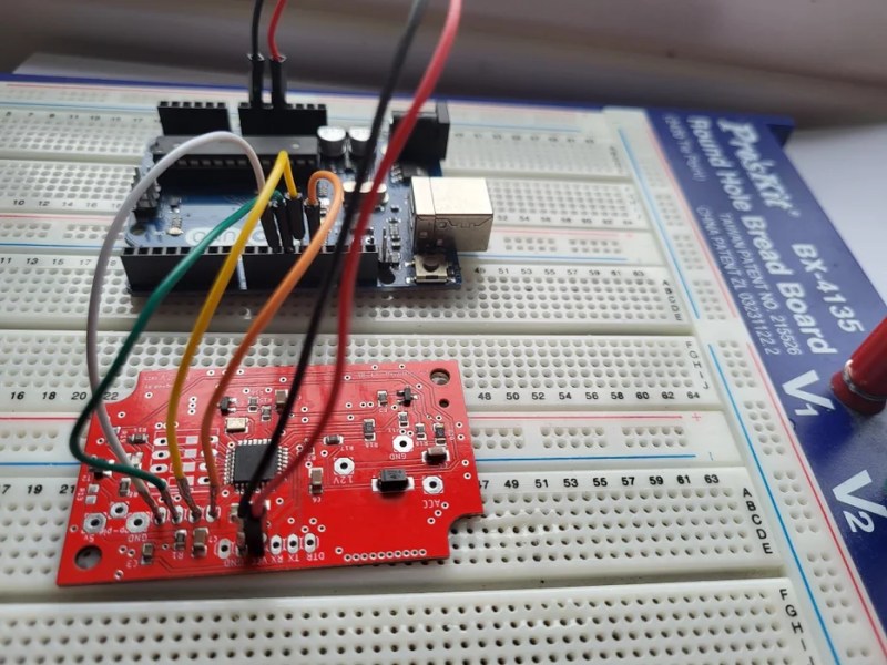
He found his existing dash cam from MiVue consumed 3.5mA in idle which works out to be a whole amp-hour every 12 days. The custom version takes just 50uA which means it will draw an amp-hour in two years. The brains of the chip are formed by an ATmega328 and an LM2596M, which is a simple step-down regulator. Interestingly, [Kuzysk] purchased clones and original chips and found that the cheaper clones had a lower switching frequency but a much lower power draw. Programming an Arduino bootloader onto the board is fairly straightforward and [Kuzysk] kindly provides his code. It can detect the ACC voltage that’s on when the engine is on and is powered by a permanent 12v connection to the battery.
Overall it’s a straightforward hack that goes through rolling your own Arduino, optimizing for low power, and putting it all together into a polished project. Perhaps for the next version, he can use the ATmega to control a cheaper camera and make it smart.
Thanks to [Microchip makes] and [Abe] for the tip!


Got a broken link to instructables.
Correct link is:
https://www.instructables.com/Dash-Camera-Power-Supply-With-Ultra-Low-power-Off-/
and not
https://www.instructables.com/Dash-Camera-Power-Supply-With-Ultra-Low-power-Off/
There’s a – missing at the end.
https://www.instructables.com/Dash-Camera-Power-Supply-With-Ultra-Low-power-Off-/
I bit clickbaity for my tastes. I was thinking about an always recording dash cam, but it just cuts the “standby” draw. While still impressive, it’s not what the title made me believe.
I have two dash cams for my cars, and they are plugged on a USB socket that is not powered when the car is off, so no matter the standby draw, it would not affect my car at all.
Thanks for saving me the click on the link. This sounded highly suspicious right from the start, yes.
If he can drive his car for 12 days, I’m pretty sure it’s unnecessary.
Interesting… but if it’s not actually recording while the engine’s off, and it’s just monitoring the voltage to see when it starts… why not just connect it to the ignition switched circuit so it draws 0ma when the car’s off?
The dashcam I have has a supercap to allow it to flush to card after the input power is disconnected, I guess this one doesn’t…
Actually it’s cutting power when the battery gets low. That means the dashcam is actually recording while the car is off, but if the battery gets low after a day or two it will cut the dashcam off.
You have to go to the article, the HaD article kind of masks the real case.
3.5 mA is insignificant.
Any modern car draws far more than 3.5 mA in standby current even without a dashcam, with keyless entry and security systems running 24×7.
It’s not when it’s *added* to the nominal draw – for those of us who leave cars for weeks on end, it can mean the difference between getting back off a flight and finding a flat car and damaged battery, or not.
A typical 50 Ah car battery can supply 3.5 mA for well over a year and still have enough amp-hours left to start the car.
3.5 mA is insignificant compared to other standby loads. I’ve measured 30 – 80 mA (Subarus, Mazda) and a whopping 250 mA (BMW).
If your car battery is dead after a few weeks on standby you have a problem (or a BMW).
My VW Van has constant 12V on cigarette lighter socket. I have several dashcams and most of them will sense 12V vs 13.8V when engine is running and turn dashcam on and off. At least Cobra dahscam does.
Actually same concept was already for the factory radio. There is no ignition or accessory wire. Just 12V.
I wonder how that works with EVs where there is no alternator, only a DC-DC converter. I don’t know if any of them emulate the higher voltage when “running”. The ones I’m familiar with tend to top the 12V battery up on a schedule, rather than when you are driving, so the camera would think it was on during 12V charging at random times.
The battery hits a low threshold and is charged. Hits the high and stops. It wouldn’t really matter you could leave it on for quite a while. Even at 10% main battery our car has 7kw available. Have had Nissan and now Tesla will keep the 12v charged it won’t power up to drive without it.
It’s more likely that your radio, especially if it’s OEM, is switched by the canbus and not current sensing
Good point!
Looking at the code it’s not doing any sort of deep-sleep on the microcontroller. How is this only drawing 50uA with the processor running? Guessing it’s only drawing that when the car battery is low and it switches its own dc-dc converter off (thus powering down the micro too). It’s such a weird schematic as well.. hard to tell how the heck it’s supposed to work.
Yep, looked through the code and it never puts the micro to sleep so the 50uA figure is definitely not when the micro is actually running.