Tinkercad is like the hamburger helper of 3D design. You hate to admit you use it, and you know you should put in more effort, but — darn it — it’s easy, and it tastes pretty good. While I use a number of CAD programs for serious work, sometimes, when I just want a little widget like a flange for my laser cutter’s exhaust, it is just easier to do it in a few minutes with Tinkercad. However, I heard someone complaining the other day that it wasn’t of any use anymore because they took away custom shape generators. That statement is only partially true. Codeblocks allow you to easily create custom parametric items for use in Tinkercad.
There was a time when you could write Javascript to create custom shapes, and it is true that they removed that feature. However, they replaced it with Codeblocks which is much easier to use for their target audience — young students — and still very powerful.
If you’ve used parametric design in a professional package or even used something like OpenSCAD, you probably don’t need to be sold on the benefit. This is, of course, a simple form of it, but the idea is to define things as mathematical relationships. As an example, suppose you have a front panel with two rows of four holes for switches evenly spaced and centered. That would be easy to draw. But if you later decide the top row needs five holes and the bottom only needs three, it will be a fair amount of work. But if you have the math defining it right, you change a few variables, and the computer does the rest.
The Third Thinkercad Thing
When you go to the Tinkercad website, you probably notice there are two extra selections in addition to 3D design. One is Circuits which lets you build and simulate simple electronic circuits that include Arduinos and other items. The other item is Codeblocks. You might assume that is a way to program the Arduinos in the simulation, but that’s not what it is. It turns out there is something very similar in the circuit simulator for that purpose. But Codeblocks is for creating new parts for use either on their own or as new parts within Tinkercad.
If you are familiar with OpenSCAD, the idea is that it is sort of Scratch and OpenSCAD merged together. Sort of. There are a few things that are, perhaps, less than ideal, but overall, it works well. The block language doesn’t have some things like if/then/else statements. Handling variables is a bit clunky, but possible. The way you produce reusable parts is very wacky, but once you get used to it, it isn’t bad.
But the worst part is that there is no “round tripping.” That is, suppose you create a template for a bracket and you produce one that is 10 cm long in your Tinkercad design. Changing the bracket design won’t update the existing design. You’d need to export the part, delete it from the design and put it back in. Of course, that can also be a feature, depending on how you look at it. Changing a part tomorrow won’t mess up your design from three months ago. But when you are tweaking a design, it is a bit annoying.
Getting Started
Like all things Tinkercad, the user interface is very colorful. You’ll see a shape palette to the left, a workspace in the center, and something that looks suspiciously like the Tinkercad workplane on the right. If you try to do things over in the right panel, you’ll be frustrated. It is just a preview. You can do anything significant there other than shift your viewpoint.

The top strip has a slider labeled “Speed,” a play button, a step button, and a reset button. There are also buttons for export and share. Most of the time, you will want to jam that speed slider all the way over to the right, but if you are trying to debug something, you might want to slow it down. The step button just goes one step at a time, regardless of the speed.
Programming
The tools and the blocks they make are color-coded. Blue items are shapes just like you might find on Tinkercad’s normal screen. When you drag the block over to the middle pane, you’ll see some parameters that look like slots for numbers. It is true that you can change those default numbers with other numbers, but you can also put certain other blocks inside.
The purple tools all modify objects. You’ll use these often as everything is in the center at first. If you want it somewhere else, you use the purple Move block. There are also blocks that can rotate and all the other things you expect. The Create New Object block is also important but tricky, as you will see.
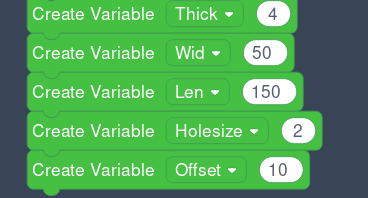
Orange tools are controls and offer two types of loops. One is a simple repeat. The other is like a for loop and creates a variable you can use. Green tools do math operations, while light blue tools represent variables. You use the green Create Variable block to make a variable. Oddly, the variable is always called item, and then you can rename it to something else. Just be careful: if you make, say, five blocks that create item and rename one of them, you will rename all of them! So rename as soon as you drag one block over, and don’t call any of your real variables item.
The final group is just comments and debug messages. Those are trivial but great for documentation and debugging.
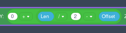
The variables and math blocks are the keys to making things parameterized. Consider this:
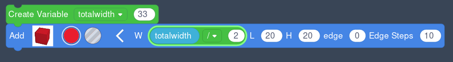
Here we have a variable. In the shape, I dragged a math block in and then dragged the variable from the “data” section to the first slot in the math block. Then I changed the operation to divide and set the other slot to 2. It is tricky; you have to watch the cursor preview to see where things will drop, and it is even trickier when you want to replace things. As you drag, the part you are dropping into will light up. It is possible to, for example, drop something into the math block or drop something that will replace the math block. Anything that gets replaced usually winds up detached and behind everything. It is usually harmless but still annoying.
Value
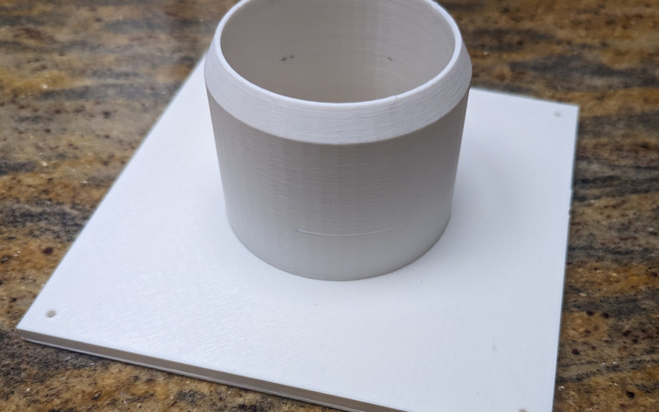
Of course, if you just plug numbers into shapes, there isn’t much value to that. The big payoff is when you want things to move and resize independently or you want to step and repeat using loops. Another valuable technique is creating a template that you can then use over and over again. Here’s a simple component that illustrates all of this:
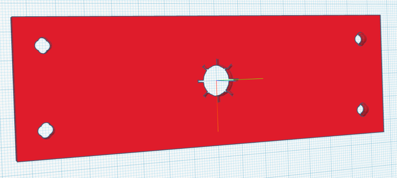
The idea here is that the four “clover leaf” holes should be inset from the corners of the plate, no matter how big or small it is. The “star” hole in the center should also adjust based on size.
You could, of course, just manually create all the features using these variables, but that’s not really the point. Instead, I’ll create several new objects using Create New Object. The objects are: slot4 (the clover leaf slot), Star (the center star), and object0 (the main object).
Here’s the problem. When you tell the program to create a new object, it just groups things together. But it still draws them in the center of your workspace. What I have found works well is to think of these parts as “templates” and then use the Add Copy of Object block to actually make a new instance of the object.
Codeblocks run from top to bottom, so the templates must be physically above where you want to use them. Then at the end of the whole thing, I’ll use Delete Object to remove the templates.
In this case, the sequence of events will be:
- Create the clover leaf hole template
- Create the star hole template
- Draw the box
- Copy the clover leaf template as a hole four times and move it to its final location
- Copy the star template as a hole
- Delete the templates
- Group everything together
 You can find the code online if you want to try it yourself. It is important to remember that everything is centered at point (0,0,0) until you move it. So expect to divide things by two a lot. It is often handy to set up a nested set of math boxes you can duplicate that looks like this.
This way, you can take a point and make it positive or negative, scale it, and offset it all in one block. You’ll note the center hole uses a for loop, which provides variable i. Even though the star has eight points, the code loops four times. Since the box that forms the star’s arms rotate around the center, each time through the loop creates two opposite points.
To Tinkercad
If all you needed was the plate, then you are ready to go. Press Export, and you can create an STL, OBJ, or SVG. However, one of the other options is “Shape.” That’s how you get it into your Tinkercad tool palette. You can give the part a name, a description, and a color. Optionally, you can lock the part size so no one can rescale it in the normal Tinkercad editor.
Once you finish the export, the part will appear in the normal shape library under “Your Creations.” You can place it like any other Tinerkcad shape, and if you allowed it during the export, you could resize it there.
So while the custom shape generator is gone, its spirit lives on in Codeblocks. Is it perfect? No. Honestly, if I were just going to do the whole part like this, I’d probably turn to OpenSCAD. But if you need to support custom shapes in Tinkercad, Codeblocks is perfectly serviceable.
Think Tinkercad is just kid stuff? [Jay Doscher] begs to differ. You can even do simple physics simulations in the tool.


The only reason I use TinkerCAD and sticking with it for now, is because it’s not parametric. My head doesn’t allow me to work in reverse. I know other software applications can create much more powerful 3D renderings for me and maybe I will change in the future, but I tried many different pieces of software and even using tutorials it’s painful for me to use them. Creating 3D objects in 2D and then changing dimensions into 3D again, like I see in tutorials for OpenSCAD and competitors, just doesn’t work for me. It has limitations and I’ve ran into many of them, but it’s so easy to just fire up TinkerCAD and do the work there. I just redesigned the guage cluster for my motorcycle in TinkerCAD. Going to try to print it out this weekend.
> Creating 3D objects in 2D and then changing dimensions into 3D again, like I see in tutorials for OpenSCAD
OpenSCAD allows that, but it isn’t necessary. I’ve never done it. When I use OpenSCAD I do a boolean workflow of removing and adding material to create the part.
Parametric modeling doesn’t have limitations.
Indeed. I eschewed tutorials because the possibilities of parametric/solid modeling design are immediately apparent.
I can understand, though. If I had hit the tutorials before diving in (with some functional programming experience, for OpenSCAD in my case), I might not have realized the power and flexibility of it.
I prefer OpenSCAD. Its OpenSource. Its GUI hasn’t changed in years. We can run it on Windows and linux. It outputs STL files that we can 3D print. And I can type so its relatively fast.
// OpenSCAD Flange
// by KSanger
// Define your parameters.
TOL = 0.2; // for my MK3 with 0.2mm layer height.
FN = 100; // To smooth out cylinders.
FLANGE_H = 3; // all units in mm.
FLANGE_WIDTH = 2*25.4; // lets make our flange 2″ x 2″.
OD = 25.4; // 1″ OD
ID = OD-0.125*25.4 + TOL; // Sometimes I use 2*TOL
ID2 = ID + 25.4/16; // bevel the top
TOTAL_H = 25.4; // 1 inch = 25.4 mm…
BEVEL_H = 0.125*25.4; // 1/8 inch bevel height.
MOUNTING_HOLE_D = 0.268*25.4; // 1/4″ clearance hole diameter.
MHD = MOUNTING_HOLE_D;
MOUNTING_HOLE_INSET = 0.25*25.4;
MHI = MOUNTING_HOLE_INSET;
module flange() {
difference() {
union() {
// flange
translate([-FLANGE_WIDTH/2,-FLANGE_WIDTH/2,0])
cube(size=[FLANGE_WIDTH,FLANGE_WIDTH,FLANGE_H]);
// Outer cylinder up to the bevel.
cylinder(d=OD,h=TOTAL_H – BEVEL_H,$fn=FN);
// Top Bevel
translate([0,0,TOTAL_H-BEVEL_H])
cylinder(d1=OD,d2=ID2,h=BEVEL_H,$fn=FN);
//
}
union() {
// Subtract the inside diameter
translate([0,0,-0.1]) cylinder(d=ID,h=TOTAL_H+0.2,$fn=FN);
// Note we want the subtracted part to be through the whole part and not
// end on a side wall as then the SW would not know what to do with a
// remaining surface with zero width.
// If you want to put holes in your plate you add them here
translate([-FLANGE_WIDTH/2+MHI,-FLANGE_WIDTH/2+MHI,-0.1])
cylinder(d=MHD,h=FLANGE_H+0.2,$fn=FN);
translate([FLANGE_WIDTH/2-MHI,-FLANGE_WIDTH/2+MHI,-0.1])
cylinder(d=MHD,h=FLANGE_H+0.2,$fn=FN);
translate([-FLANGE_WIDTH/2+MHI,FLANGE_WIDTH/2-MHI,-0.1])
cylinder(d=MHD,h=FLANGE_H+0.2,$fn=FN);
translate([FLANGE_WIDTH/2-MHI,FLANGE_WIDTH/2-MHI,-0.1])
cylinder(d=MHD,h=FLANGE_H+0.2,$fn=FN);
}
}
}
/* run your module. I use modules to build one part at a time then combine or
* subtract them. We also use the hull() operator a lot to build rounded corners.
* And if you subtract rounded cubes you can generate inside bevels.
*/
flange();
// Enjoy
Oh yeah, I do like OpenSCAD also (wrote a book on it, even). But teaching kids with Tinkercad is significantly easier.
OpenSCAD has an advantage in that it teaches them to program at the same time they’re creating 3D objects, a general skill which can be transferred to other programming languages unlike the often steep learning curve which is specific to each 3D design program (although not TinkerCAD).
Oh gosh please no. Don’t teach people programming with OpenSCAD. The concepts used in OpenSCAD do NOT translate to regular programming, and we have enough people who learned programming from some wonky source and can’t write decent code to save their lives.
If I interview another NCG who “learned programming” from making Minecraft mods, I am going to flip. It’s cool you are an expert on a specific niche form of programming, but you have no idea how to structure a program or implement an algorithm.
Sorry whats NCG?
I learned Java, not programming could do that before that, from writing Minecraft Server Plugins back in the hMod days way before Bukkit and Canary, does that count because it was “the hard way”? ^^’
No. Bonafide programming language theorist here. OpenSCAD has a beautiful functional language. I think we’re butting up against the imperative/functional (lazy) divide here.
I’m personally a CadQuery (python library) advocate. OpenSCAD is great, but I’d rather not learn another language (even a simple one), and I hear it has some pretty nasty issues around namespaces (or rather, lack thereof), making libraries hard to manage (not a huge issue for my usual workflows, but I’d rather avoid such a large-caliber footgun). You also get the whole Python ecosystem to lean on, whether for math libraries, FEA, statistical analyses, etc.
That said, both are great tools! Whatever works, works.
I had some problems using cadquery because it has some rather un-python like behavior. If I remember correctly, when I created an object as a variable, and then modified that variable, I ended up with two objects…
I’m using solidpython2 instead. Extra bonus point: you can just pip install it. (I had to use a docker container to get cadquery to run on my system…)
I think I ran into something similar with the mutability thing, but I shifted to a more procedural treatment of the objects where, instead of treating them as mutable, I’d return an object after an operation on it. A super natural adjustment for my personal coding style, I understand the gripe, though. I suspect the OpenCascade kernel doesn’t play nice with some pythonic mutability patterns.
I definitely didn’t have to run it in docker. I suspect you had a dependency conflict, a common issue and why virtual environments are considered best practice for python. Docker would solve that, but so would something lighter like venv, virtualenv, or Conda (what I used, following CadQuery’s documentation). This is why I now am a dirty rustacean for anything the ecosystem supports (no friendly CAD crates I’ve seen yet, though there are a couple ground-up kernels that may eventually be something), Cargo is king.
It looks like solidpython2 generates OpenSCAD code. CadQuery instead manipulates OpenCascade objects. I imagine there are pros and cons to both, I know I have issues with the OpenCascade kernel. It seems like, as long as you control your library structures in Python, you could avoid the OpenSCAD namespace issues. I also imagine you could put thin Python wrappers around well-developed OpenSCAD libraries (it is the most used scripting CAD system, after all!). Good to know there’s a viable alternative! Maybe I’ll play around with it for my next project.
Hm, looks like the scad crate does the same for rust! Never mind, back to my haven of cargo-managed dependencies I go!
I’ve been using scad-js with a modified template to do everything in typescript, way better ergonomics, and, lsp works flawlessly.
scad-js: https://github.com/20lives/scad-js
template: repo https://github.com/scad-js/scad-js-starter
Very mInor issue: you’re stacking one cylinder on top of another with no overlap. Isn’t that asking for trouble, maybe like a thin surface between the two cylinders due to round-off error? When I stack cylinders, I always nudge the upper cylinder down by a tiny amount, say 0.001. (Which has a weird edge effect at a micro scale.)
Lately, I’ve realized that it’s easier to just use rotate_extrude() and polygon for things like a hollow beveled cylinder:
rotate_extrude() polygon([[OD/2,0],[OD/2,TOTAL_H-BEVEL_H],[ID2/2,TOTAL_H],[ID/2,TOTAL_H],[ID/2,0]]);
No subtraction, no nudging, superfast rendering. And if you ever want to upgrade to a smoother bevel, you can replace the arguments of the polygon with the output from a Bezier library.
Similarly, it’s easier to do the base plate as a 2D rectangle with holes (no nudging the hole cylinders to stick out above and below the plate) and then linear_extrude().
Module awesome comment() {I agree}
// I think I might start writing in Openscad more widely.
Select rendering quality, first line of file.
$fn = $preview ? 23: 100;
There have however been a couple of graphical interfaces created on top of OpenSCAD:
– clikscad (see the archives of the OpenSCAD mailing list)
– graphscad (should come up on a search on blogspot)
– BlocksCAD: https://www.blockscad3d.com/editor/
– OSGE (OpenSCAD Graph Editor): https://github.com/derkork/openscad-graph-editor
The latter is esp. promising, since it encompasses the entirety of the OpenSCAD language.
You should NOT be teaching kids Tinkercad, and entrapping and brainwashing them into Autodesks’ ecosystem.
I’d go a step further and say you shouldn’t be teaching kids to use a specific program at all….
Instead you should be teaching them the basic concepts, and once they have grasped them, they should be able to apply the concepts to any program.
Yes!
Yes, as someone who recently took “engineering” in high school we always spent lots of time drawing out designs on paper, three view, isometric, unfolded nets. Being high school students we would all moan and groan, however when it came to model in any CAD program — for us Solid(doesn’t)Works. It was self evident who actually did the drawing practice from the lack of frustration at converting into 3d from sketch.
Paper first, then cad. If you can convert between 3d representations, you just have to learn what icon represents what in each CAD program.
> If you can convert between 3d representations, you just have to learn what icon represents what in each CAD program.
There is a little more to it than that – to do CAD properly requires working to the best practice of that specific software, as they all have different gotcha’s. And some of that is at the relatively basic order of operations level, where there is no reason other than the programs limitations to do it that way.
Though I also think getting people to use many different methods to really learn the unpinning logic and ideals behind the methods is worthy. But for that I don’t see Tinkercad as a problem, it is a perfectly valid way to create a 3d object to your specification.
You can’t do this (reliably) with kids. Until humans reach the “formal operational” cognitive development level, we have a lot of trouble grasping concepts without first seeing examples. Tinkercad is a great way to get right into some examples, without having to understand all of the complexities of a powerful user interface with lots of menus containing big words.
I’m not a tech drawing professional by any stretch of the imagination, but I use both Fusion360 and Onshape (for their parametric capabilities mainly) and I can do what I need fairly quickly. However, it took me several attempts to learn these, because I didn’t know enough about the fundamental concepts of 3D CAD. I learnt these concepts on Tinkercad, while also being somewhat productive there. Then went back to F360 and Onshape, where it all made much more sense.
2nd this.
I teach at the Middle School level and have used both Tinkercad and AutoDesk Inventor in the classroom with students. I use Fusion 360 and SCAD for personal projects.
In addition to the cognitive piece, younger students (~14 years or younger) benefit from smaller ‘chunks’ of information and Tinkercad is great at gettings students making something with very little front loading of instructions. Once students see their efforts pay off they are excited to learn how to do it better and will retain additional instructions.
In contrast: Inventor requires significant front loading of concepts and procedures that many students will struggle to retain, and then when they don’t get the results they expect feel frustrated and give up. This is not solely the fault of requiring ‘immediate gratification’ but is developmentally appropriate for their age. As students age they get better at long term planning and will have more life experiences for which to link the new information to. (check out zone of proximal development for more about how that works).
This, a thousand times. Software are retired, even Open Source ones can become unmaintained for various reasons, but concepts remain. Kids should be helped first to identify the goal, then to choose the right tool for the job by not being tied to a specific one.
I love tinker cad. I have designed so much with it. Looks like a kids toy but is more than enough to design anything the average maker needs. I even designed and printed a 100% (except for the electrics) 3D printer and it worked perfectly. Showed it off years ago on Adafruit show and tell. During lockdown I used it to design and print all the parts needed to turn my 25 year old push bike into an e-bike.
I wish Microsoft would add a parametric or script driven component to 3D builder. It would be nice to scale a part while retaining the same size of holes and other spaces.
Each to their own I say … and what you get used too. I found FreeCad and just stuck with it. It works fine for what I need it to do … and ‘lots’ more to learn too as I go along. Also it isn’t browser based… a major win also. I’ve designed a part or two with OpenScad which is interesting (I am a professional programmer), but fall back to FreeCad for more complex parts. Just me though. Each of us have different ways of learning :) .
There’s no way I’d waste a single second sinking effort into a web-based work environment of any kind, that can go away or lock me out at any moment. Nor use a “free” offering of some proprietary tool for the same reason. So far there was nothing I couldn’t get done with Solvespace – then again, that’s just my experience, YMMV…