Nothing beats a laser cutter and a sheet of Baltic birch plywood or MDF when it comes to making quick, attractive enclosures. Burning out all the pieces and fitting them together with finger joints is super satisfying — right up until you realize that you didn’t quite get the kerf allowance right, and your pieces don’t fit together very nicely. If only there was a way to automate kerf measurement.
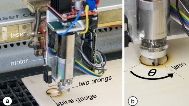
There is, in the form of Kerfmeter. It comes to us by way of the lab of [Patrick Baudisch] at the University of Potsdam, where they’ve come up with a clever way to measure the kerf of a laser cutter right during the cutting session. With the Kerfmeter mounted directly to the laser cutter head, a small test artifact based on an Archimedean spiral is cut into a corner of the workpiece. Pins on a small motor engage with the object and turn it until it jams in its hole; the wider the kerf, the greater the angle. Once the kerf is calculated, the rest of the design can be dilated by the proper amount to achieve a perfect fit. The video below shows it better than words can explain it.
What we like about this is its simplicity — all it involves is a motor and a microcontroller, plus a little software. It seems much faster than using a traditional kerf gauge, not to mention more precise. And while it does use up a little bit of material, the test pattern is really pretty small, all things considered. Seems like a reasonable trade-off to us. Still, if you want to figure out your kerfs the old-fashioned way, we’ve got you covered.
Thanks to [Leif] for the tip.


It occurs to me you don’t even need the special attachment. Marking a scale on the board and reference mark on the disc would allow you to turn it by hand, measure how far it turned, and input that value into your control software. Probably not as accurate as a motor with a decent encoder and repeatable amount of torque, but I suspect that wouldn’t be needed in most cases.
It’s a neat idea, basically a cam in reverse. It’s not something you need for every job, if the material is the same then the kerf is the same.
Your scale suggestion would work fine, after all they’re just converting angle to kerf in software so not hard to add a scale.
These people seem to on the “Mt Stupid” part of the learning curve, there’s quite a few traps waiting for them, eg longer slots require a wider kerf as there’s more friction and so on.
On the other hand, the kerf is unlikely to change a lot once the machine is set up, so you can just cut a square and measure the resulting dimensions with digital calipers – compare to what you expect to get and subtract for difference. Even if this takes a relatively long time, you only need it done once per N number of boards cut, probably just once every time you reset the optics.
Even if it takes you 2 minutes, per 100 boards it’s just 1.2 seconds extra setup per board. If this was a production setup, you would be measuring the dimensions of the cut parts by periodic sampling anyways and feeding that back to your software continuously as they come out.
While a cool build, I see a bunch of failure modes. Like the inset circles not dropping down (various causes, but one of them being the air assist causing the inset to jam sideways)
Assumes you have zero backlash.
Assumes you don’t want to adjust your kerf for press fit or lose fit.
Assumes your kerf value will change for some unknown reason. In my experience, you measure this once and use it always.
The exact value isn’t that critical. You don’t need that resolution.
The stats are compared with a very inefficient method. Can be done with a single wedge in a small slot, or a small square and some calipers.
The piece shouldn’t be dropping down, that implies the sheet isn’t flat etc. Laser cuts have a small bevel, and that’ll throw out the reading slightly.
Wait until they discover plastic doesn’t have uniform thickness, that’s really annoying. Maybe they’ll decide to do a kerf test on each corner and average it (a bit like 3D printer bed levelling).
At that point, you may as well use a (well filtered!) camera to continuously monitor and control cut kerf curing cutting. A telecentric lens should allow for accurate off-axis metrology, or multiple angled cameras at the carinal directions to get reasonable coverage from multiple cut directions and use cosine of the gap width to calculate just-cut kerf width (a few mm behind the actual cut, but probably good enough for most material variation).
Seems like less effort – and probably cheaper – to mechanically thickness material prior to laser cutting (or be more stringent with QC and stock rejection), though.
The varying thickness of acrylic doesn’t affect the kerf, it becomes a problem when trying to join pieces together – oh, it’s too thin / thick for the slot.
And when I say varying, I mean over 300mm one corner might be 0.2mm different.
And good luck trying to run plastic thru a thicknesser or whatever you were thinking.
I was wondering about how this works with the ‘fit’ but I assume all the calibration system is doing is correcting for the ‘tool size’ this particular laser and material combination effectively creates and so adjusting your cut lines to actually cut where you expect them to – as in you would design your part as press fit or snug but with gap for glue fit and it actually produces that specified designed size…
Though how it can know which side of the line is important at any given time I don’t know – don’t want to go offsetting your cut to correct for the cut width into the part rather than the waste stock… I suppose in nearly all cases the outer perimeter of the shape cut is supposed to define the outer perimeter of a part, but sometimes you will be cutting voids where that shape is effectively an inner perimeter…
This to me seems like a useful calibration tool, but one that should only ever be run manually and the correct adjustments entered into your parametric model before it is sent to the machine – as you actually know which dimensions are critical in which way. Also it doesn’t really seem to deal with how out of square the cut may be, which could matter if you go flipping some parts relative to their mating surfaces – the fancy and correctly set up laser cutting machines really don’t need to worry about that as they can cut really damn square even through thicker materials but your cheaper hobbyshop end that is probably not focused perfectly… Though if all you are cutting is wood or foam type soft materials it really won’t matter as much being a more compressible material as long as the fit is not way way too tight you can push it home.
It won’t work for simple vector drawings, because simply scaling the part uniformly will grow those finger tabs and slots as well, instead of making them slightly smaller.
Rest assured CAM software has addressed the problems imagined here.
Clearly software designed to receive ketf information dynamically will be working from a model to accommodate the information.
A good addition would be to have a round circle to verify that X and Y axes are square to each other. Otherwise this test will show wrong values for the kerf, and of course pieces come out wonky also.
0.16mm is the kerf for pretty much every hobby CO2 laser cutter in 3mm material. Add / subtract 0.005mm for tighter / looser fits.
For stuff like EVA foam you’re looking at more like 1mm kerf as it melts a lot, never bothered to see what it actually is.
I don’t have a laser cutter, and though I agree this is a pretty inventive method of kerf measurement, I have doubt it has a lot of practical use. First, how often do you need to make this measurement? Bob (above) suggests there is very little deviation of the kerf, even with different materials. And even if there are differences, then just make a table once, and add new materials to it when you get them.
The difficult thing about automation is that things have to work perfect to be reliable. If it’s not reliable, then you still have to babysit it, and it would hardly be better then making a square or rectangle and measuring it yourself with calipers, or as Doug mentioned, also burn a scale on it and then enter the last
And as Daid already mentioned, there are lots of failure modes.
The need to position the round holes above holes in the grating (@01:10) makes positioning of the kerf spiral difficult. In the video a lot of material is wasted for this kerf measurement spiral. If positioning was non-critical, it could have been put inside the big circle in one of the squares. This makes the notion of “25x less material (4cm2 vs 100cm2)” (@02:13) laughable. Alignment for inserting the pins (@01:21) was also off a bit, and it almost failed to insert the pins.
Some ideas for possible improvements:
* Can the circles be burned completely instead of just cut out, or would that increase the risk for fire too much? (Probably works better with air assist, I think this blows out any flames).
* Centering of the round pins in the round holes is quite critical for the angle measurement. Having straight edges probably works more accurate.
* It could be made a linear wedge. Then you do not need a motor to turn the spiral, but you can just use a pin and and axis of the laser cutter to move the wedge. (Add a load cell or spring with switch for force measurement).
Usually when I cut with a laser, I don’t want to waste a whole board so I throw in some off-cut that’s just large enough for the pieces, or a board that’s already been cut and select a point where the parts fit. When you don’t have a lot of material to work with, finding a suitable spot for calibration slows you down considerably.
The kerf never changes, why would it? It’ll change with materials (esp with thickness) or a different lens (focal length changes) but there’s no reason to continually check it.
Typical C02 laser kerf is 0.16mm, so if you cut a 10.16mm square it’ll end up being 10mm. If you are doing things that slot together (like their finger joint box) you add a little fudge factor to loosen up the fit, so for 3mm material you don’t want exact 3mm slots, you want them say 3.05 – 3.1mm, otherwise the fit is too tight.
It’s not the kerf that’s important, it’s the fudge factor for fit you want, that’s what @Phil Barrett below is referring to.
The main problem with this is they’re trying to accurately measure something that’s rather small. The best way to measure something thin is to measure a pile of them and then divide by the quantity.
This dude almost gets it right: https://youtu.be/InYJ3_mugxI?t=275, but don’t measure the small gap, measure the length of the squares and take that off what the drawing was. So you drew 10 x 10mm squares and measured the cut ones at 98mm, divide that missing 2mm by 10 and your kerf is 0.2mm for that material. Simple.
And he cut some lines twice (overlap), that’ll screw up his measurement as well. Doh.
People keep inventing the wheel poorly or do the cargo cult thing.
Clever idea. However, it’s a lot easier to make a simple fit tester – just cut a bunch of slots of varying widths and see which one fits the best. I’ve used an increment of 10 mils/0.25mm to good effect. Then adjust the slots in your CAD/CAM app. If your CAD has parametric design support, it becomes super easy.
If you are interested in this method, you _absolutely_ need to read the paper. They’ve thought of literally everything. A lot of the “cool, but…” comments here are almost absurdly thouroughly addressed.
For instance, they’re getting precision in kerf measurement that exceeds the machine’s precision. To the point that they discover that kerf varies measurably across the bed, systematically, on the three different cutters they’re testing.
How tight do you like your finger joints? This method lets you specify that, in Newtons. It’s like showing a plumber a torque wrench for the first time.
Because there’s no literature about how tight finger joints should be, they actually go and ask a bunch of students to put boxes together, note at what pressures they fail to assemble the joint, and rank their favorite fits, which they quantify here.
TIL: College kids can’t reliably assemble box joints that require > 100 N of force.
In short: this paper is sciencing something that I’ve never seen scienced. And automating it to boot. With a crazy cool mechanism. Damn!
> This method lets you specify that, in Newtons.
I highly doubt that, since wood expands by humidity and temperature. It’s not a stable enough material for the precision they’re claiming.
Too bad we can’t control humidity and temperature in enclosed spaces…
As one of the “cool, but…” brigade, I can say I learned nothing new from reading the paper. They’ve confirmed what is already known, which is nice.
eg they found the kerf averaged out at 15.5um, which is suspicious close to the ~0.16mm number I said is the kerf for most CO2 lasers.
Also they found a few ways people measure kerf, none of which is the way you should be doing it.
As I said in another comment, kerf is irrelevant and doesn’t change anyway. They’re looking for tolerance, which affects fit. That’s what those slot test things are for, checking how sloppy the tolerances are.
The way I do my designs is set the finger size and then add on the tolerance (aka clearance), so a 6mm finger might be cut 6.05mm. You then take that drawing and add the kerf offset. Note that for bigger boxes or deeper fingers (slots) you’ll need to increase the tolerance, that’s just the way it goes and I didn’t see any discussion on that.
They’ve invent a wheel without bothering to ask any wheel makers how they do it.
Using the spiral is absolutely brilliant. Just reading the description I realized it was brilliant. I do ponder if you could use a specialized mechanism instead of attaching it to the cutter head in order to make modifying existing systems easier.