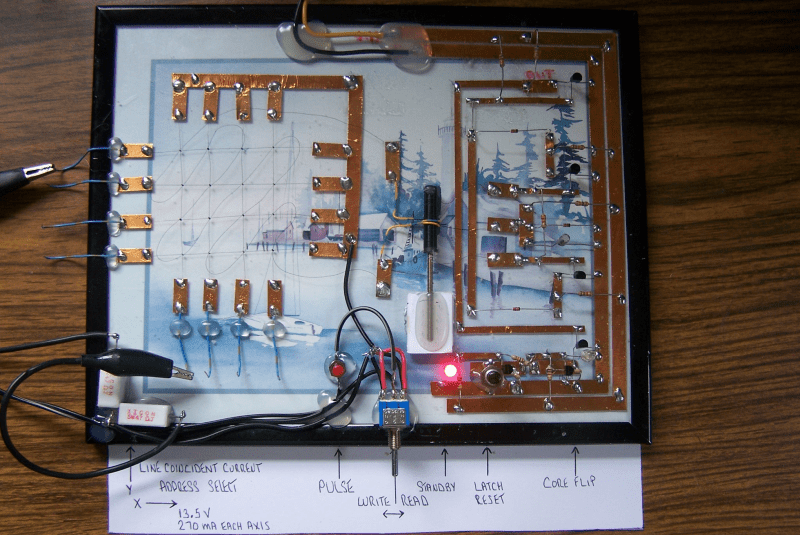
No matter how memory technology marches on, magnetic core memory is still cool. Radiation-hard, nonvolatile, and so pretty. What’s there not to love? [Mark Nesselhaus] is no stranger to fun in-your-face electronics builds — judging from his hackaday.io projects — and this entry to the Hackaday Op-Amp contest is no outlier. This is a sixteen-bit magnetic core RAM demonstrator built upon glass using copper tape and solder, which always looks great and is actually not all that hard to do yourself provided you grab a new scalpel blade from the pack before starting.
For the uninitiated, the crossed X and Y wires each host a hard magnetic toroid which can only be magnetised by a field beyond a certain threshold due to the shape of the B-H curve of ferrite materials. The idea is for a required threshold current, drive the selected X line and Y line each with a current half of this value, so that only the selected core bit ‘sees’ the full field value, and flips state. This means that only a single bit can be written for each core plane, so to form longer words these layers are stacked, producing some wonderful cubic structures. These magnetic circuits are responsible for putting a human on the moon.
Reading the bit state is basically the opposite. A third sense wire is passed sequentially through each bit in the array. By driving a current the opposite way through the selected core bit, if the core was previously magnetised then the sense wire will read a short pulse that can be amplified and registered. The eagle-eyed will realise that reading is a destructive process, so this needs to be followed up by a write-back process to refresh the bit, although the core state will persist without power, giving the memory nonvolatile behaviour.
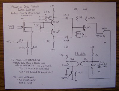
[Mark] utilises a simple discrete transistor differential transformed-coupled front end which senses the tiny current pulse and passes it along to a Set-Reset latch for visualisation. This simple concept could easily be extended to make this a practical memory, but for now, addressing is courtesy of a pair of crocodile clips and a discrete write/read pulse switch. We will watch with interest how far this goes.
DIY core memory builds are not a regular occurrence around these parts, but we see them from time to time, like this polished 64-bit setup. Core arrays are not the only magnetic memory in town, we’ve also seen DIY core rope memories as well.


Where’s the op-amp?
There is a discrete transistor op-amp after the sense line coupling transformer. Blink and you may miss it, but it is there nonetheless.
I’d call that a differential amplifier or even a threshold detector
Just to the right of the block of title text in the top left corner
Oops just noticed that’s just a symbol 🤦♂️
Heh, sorry for the small symbol. I added it as a after thought and not much room in that area of the paper.
Thanks Dave, you said it better than I did.
And you aced that circuit again, Mark !
If you sold a picture book with your framed circuits I’d legit buy it, it’s really pretty and can probably be used as a teaching aid!
You would also like the 74181 ALU I am making on glass without any transistors.
Hi, I’ve been trying to enter two designs for the op-amp challenge, and keep getting no answer. Please let me know what I am doing wrong.
The designs are here:
https://www.robots-everywhere.com/re_wiki/pub/web/Cookbook.AudioSerial.html
https://www.robots-everywhere.com/re_wiki/pub/web/Cookbook.2pin2motor.html
Attracted to your website topics but your site is full of missing images and 404s. Maybe that is why you are not taken seriously.
Yeah, we used to put pictures on imgur and now we’re hosting them locally… it’s going slow :)
Hi, I’ve been trying to enter two designs for the op-amp challenge, and keep getting no answer. Please let me know what I am doing wrong.
This allows using an audio out for a cheap android phone as a serial port for robot control (this is old, and was done before bluetooth modules were cheap): https://www.robots-everywhere.com/re_wiki/pub/web/Cookbook.AudioSerial.html
This was something we cane up with for the esp32cam module. Since pins are a premium, we needed a way to control two DC motors with only two pins. This uses a single opamp to do just that, it also does logic level shifting so that the motor driver IC can use a higher voltage. https://www.robots-everywhere.com/re_wiki/pub/web/Cookbook.2pin2motor.html
An obvious question but have you created a Hackaday.IO project, as that is where you would enter the op-amp challenge by selecting the contest entry option on the left side of your project page.
I’d rather host my stuff on my own site if at all possible!
It seems that is the answer to your question.
yes, we used to host images on imgur but as you see they are broken, we are slowly fixing them.
>yes, we used to host images on imgur but as you see they are broken, we are slowly fixing them.
No, the answer to your question, “Please let me know what I am doing wrong.”.
Read the rules: “How to Enter. Document your project on Hackaday.io.”
Thank you!
I’ve understood how the X and y currents add to a high enough current to flip a core, and that a pulse was generated in the sense wire and (somehow) detected. Now I understand the big picture!
There are a few misleading terms in this presentation. The Toggle switch labeled WRITE / READ should be labeled 1 / 0. The PULSE button should be labeled WRITE PULSE or just WRITE, and is timed by a human. For writing a bit to a core, select the appropriate X and Y wires, set the toggle to 1 or 0 as needed, then push WRITE. You can write 1’s or 0’s to a core as often or as long as you like (over-programming a core is not possible).
To read a core, reset (or clear) the latch, select the core with X and Y wires, toggle to 0, then WRITE. If the core flip LED is then lit, then the core was a 1 (it’s 0 now).
(Ever consider how Klingons in Star Trek would test a bit in their computer program? A Klingon would never ask the state of the bit, but they would command a bit to a 1 state with the response “I’m now a 1” or “I was already a 1”.)
Since the read is destructive, use the state of the LED as the bit to write back (that’s the reason for the toggle switch center position, although that part of the circuit hasn’t been built yet).
Good point but Write and Read just sits better with me but you are correct that a Write = 1 and Read = 0, at this time. I plan to later add a Write after Read logic section to refresh the bits state after the destructive Read so that is another reason for me to use Write and Read and if I do that then I will also have to add a select switch for a 1 or 0 as well as the W/R function. I had not thought about making use of the center off of the toggle but a great idea, thanks. Yes, I also got a better picture in my mind on how it all works once I got it to work. Does not take as much circuit as I first thought to detect the flip pulse but any added functions will start to complicate things a little ;-)