Op Amp Contest: Magnetic Core Memory The Dr Cockroach Way

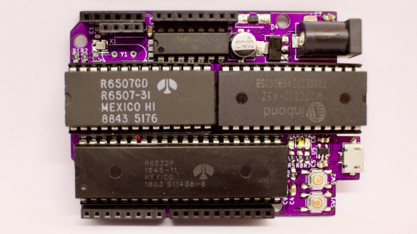
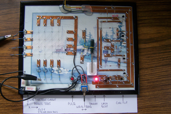
No matter how memory technology marches on, magnetic core memory is still cool. Radiation-hard, nonvolatile, and so pretty. What’s there not to love? [Mark Nesselhaus] is no stranger to fun in-your-face electronics builds — judging from his hackaday.io projects — and this entry to the Hackaday Op-Amp contest is no outlier. This is a sixteen-bit magnetic core RAM demonstrator built upon glass using copper tape and solder, which always looks great and is actually not all that hard to do yourself provided you grab a new scalpel blade from the pack before starting.

Transformer-coupled differential front-end amplifier driving an SR latch.

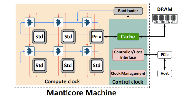
For the uninitiated, the crossed X and Y wires each host a hard magnetic toroid which can only be magnetised by a field beyond a certain threshold due to the shape of the B-H curve of ferrite materials. The idea is for a required threshold current, drive the selected X line and Y line each with a current half of this value, so that only the selected core bit ‘sees’ the full field value, and flips state. This means that only a single bit can be written for each core plane, so to form longer words these layers are stacked, producing some wonderful cubic structures. These magnetic circuits are responsible for putting a human on the moon.

Reading the bit state is basically the opposite. A third sense wire is passed sequentially through each bit in the array. By driving a current the opposite way through the selected core bit, if the core was previously magnetised then the sense wire will read a short pulse that can be amplified and registered. The eagle-eyed will realise that reading is a destructive process, so this needs to be followed up by a write-back process to refresh the bit, although the core state will persist without power, giving the memory nonvolatile behaviour.

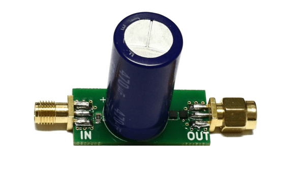
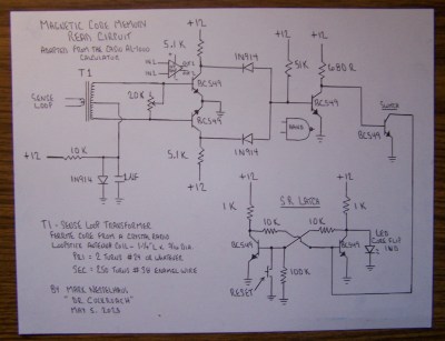
[Mark] utilises a simple discrete transistor differential transformed-coupled front end which senses the tiny current pulse and passes it along to a Set-Reset latch for visualisation. This simple concept could easily be extended to make this a practical memory, but for now, addressing is courtesy of a pair of crocodile clips and a discrete write/read pulse switch. We will watch with interest how far this goes.

DIY core memory builds are not a regular occurrence around these parts, but we see them from time to time, like this polished 64-bit setup. Core arrays are not the only magnetic memory in town, we’ve also seen DIY core rope memories as well.

Continue reading “Op Amp Contest: Magnetic Core Memory The Dr Cockroach Way”

Exploiting Hardware-Level Parallelism In The Manticore Hardware-Accelerated RTL Simulator

Before a chip design is turned from a hardware design language (HDL) like VHDL or Verilog into physical hardware, testing and validating the design is an essential step. Yet simulating a HDL design is rather slow due to the simulator using either only a single CPU thread, or limited multi-threading due to the requirements of fine-grained concurrency. This is due to the strict timing requirements of simulating hardware and the various clock domains that ultimately determine whether a design passes or fails. In a recent attempt to speed up RTL (transistor) level simulations like these, Mahyar Emami and colleagues propose a custom processor architecture – called Manticore – that can be used to run a HDL design after nothing more than compiling the HDL source and some processing. Continue reading “Exploiting Hardware-Level Parallelism In The Manticore Hardware-Accelerated RTL Simulator”

Exploring The Early Days Of QRP Radio

Morse code might seem obsolete but for situations with extremely limited bandwidth it’s often still the best communications option available. The code requires a fair amount of training to use effectively, though, and even proficient radio operators tend to send only around 20 words per minute. As a result of the reduced throughput, a type of language evolved around Morse code which, like any language, has evolved and changed over time. QRP initially meant something akin to “you are overloading my receiver, please reduce transmitter power” but now means “operating radios at extremely low power levels”. [MIKROWAVE1] explores some of the earlier options for QRP radios in this video.

There’s been some debate in the amateur radio community over the years over what power level constitutes a QRP operation, but it’s almost certainly somewhere below 100 watts, and while the radios in this video have varying power levels, they tend to be far below this upper threshold, with some operating on 1 watt or less. There are a few commercial offerings demonstrated here, produced from the 70s to the mid-80s, but a few are made from kits as well. Kits tended to be both accessible and easily repairable, with Heathkit being the more recognizable option among this category. To operate Morse code (or “continuous wave” as hams would call it) only requires a single transistor which is why kits were so popular, but there are a few other examples in this video with quite a few more transistors than that. In fact, there are all kinds of radios featured here with plenty of features we might even consider modern by today’s standards; at least when Morse code is concerned.

QRP radios in general are attractive because they tend to be smaller, simpler, and more affordable. Making QRP contacts over great distances also increases one’s ham radio street cred, especially when using Morse, although this benefit is more intangible. There’s a large trend going on in the radio world right now surrounding operating from parks and mountain peaks, which means QRP is often the only way to get that done especially when operating on battery power. Modern QRP radios often support digital and voice modes as well and can have surprisingly high prices, but taking some cues from this video about radios built in decades past could get you on the radio for a minimum or parts and cost, provided you can put in the time.

Continue reading “Exploring The Early Days Of QRP Radio”

Low-Frequency DC Block Lets You Measure Ripple Better

We all know how to block the DC offset of an AC signal — that just requires putting a capacitor in series, right? But what if the AC signal doesn’t alternate very often? In that case, things get a little more complicated.

Or at least that’s what [Limpkin] discovered, which led him to design this low-frequency DC block. Having found that commercially available DC blocks typically have a cutoff frequency of 100 kHz, which is far too high to measure power rail ripple in his low-noise amplifier, he hit the books in search of an appropriate design. What he came up with is a  non-polarized capacitor in series followed by a pair of PIN diodes shunted to ground. The diodes are in opposite polarities and serve to limit how much voltage passes out of the filter. The filter was designed for a cutoff frequency of 6.37 Hz, and [Limpkin]’s testing showed a 3-dB cutoff of 6.31 Hz — not bad. After some torture testing to make sure it wouldn’t blow up, he used it to measure the ripple on a bench power supply.

It’s a neat little circuit that ended up being a good learning experience, both for [Limpkin] and for us.

Tiny Microcontroller Uses Real-Time Operating System

Most of the computers we interact with on a day-to-day basis use an operating system designed for flexibility. While these are great tools for getting work done or scrolling your favorite sites, they have a weakness when it comes to interacting quickly with a real-world environment. For these kinds of low-latency, high-reliability systems you may want to turn to something like freeRTOS which is optimized for this kind of application and which [Parikshit Pagare] has used to build his home automation system.

This build is based around an ESP32 for which freeRTOS, designed specifically for embedded systems, is uniquely suited. There are several channels built in capable of monitoring temperature, functioning as a smoke alarm, and sensing whether someone is at the front door. All of these are reported to a small OLED screen but are also updated on an Android app as well, which happens nearly instantaneously thanks to the real-time operating system. There are a number of user-controllable switches as well that are capable of turning lights or fans on and off.

For a home automation system, it’s one of the most low-cost and fully-featured we’ve seen and if you’re still having trouble coming across a Raspberry Pi as they sort out supply issues, something like this might make an excellent substitute at a fraction of the price. If you’re looking to expand even beyond this build, one of the gold standards for ESP32-based automation design is this build from [Marcus] which not only demonstrates how to build a system like this but goes into great detail on the ESPHome environment.

Continue reading “Tiny Microcontroller Uses Real-Time Operating System”

Hackaday Prize 2023: 65uino 6502 Learning In A Familiar Package

[Anders Nielsen] presents his entry for the 2023 Hackaday Prize: The 65uino. Which as you might be able to guess, is a 6502-based microcomputer wedged into an Arduino Uno form factor (well, almost wedged in, but we’ll let it slide) The premise is simple, older micros are easier to understand, the board can be build up from new-old or salvaged stock, and that’s more chips on boards and less sitting on a dusty shelf. After all, even though the 6502 in its original form is long obsolete, it’s far better to be pushing some electrons around, than sitting there decaying.

The OLED frame buffer is bigger than the host’s entire RAM. No problem!

From an educational perspective, the first lesson is the hand-soldering of through-hole DIP components and a smattering of straightforward surface mount parts in their supporting roles.  Then on to setting up the cc65 toolchain. To say this is a pure 6502 system is a little misleading, it actually uses the 6507 device variant, which is a die-bond variant of the same device but with only 28 of the pins utilized.

The use of the 6532 RIOT (RAM-I/O-Timer) chip provides two 8-bit ports of GPIO as well as a timer and 128 bytes of SRAM, making the design more compact. There is a socket that will accept a 24 or 28-pin E(E)PROM device, with the extra four pins removable and the PCB snapped off if fitment into a standard ‘Uno case is desirable. Neat!

Full hardware build and PCB design (using KiCAD) are available on the 65uino GitHub page. Just remember folks, with everything minimal 6502 related — some assembly required :D

We see the 6502 a lot, let’s be fair. But why not? Here’s a slightly more practical board with a bit more resources, an absolute beast of a luggable dual-6502 machine, and yet another 6502 verilog implementation ready to be dropped into a spare corner of a FPGA project that needs a little extra.

Supercon 2023 Is On, We Want You!

We’re absolutely excited to be able to announce that the Hackaday Supercon is on for 2023, and will be taking place Nov 3 – Nov 5 in sunny Pasadena CA. And with that, we’d like to open the floodgates: we’d like to hear your proposals for talks and workshops! The Call for Speakers and Call for Workshops forms are online now, and you’ve got until July 18th to get yourself signed up.

Continue reading “Supercon 2023 Is On, We Want You!”