[CuriousMarc] is back with more vintage HP hardware repair. This time it’s the HP 5245L, a digital nixie-display frequency counter from 1963. This unit is old enough to be entirely made of discrete components, but has a real trick up its sleeve, with add-on components pushing the frequency range all the way up to 18 GHz. But this poor machine was in rough shape. There were previous repair attempts, some of which had to be re-fixed with proper components. When it hit [Marc]’s shop, the oscillator was working, as well as the frequency divider, but the device wasn’t counting, and the reference frequencies weren’t testing good at the front of the machine. There were some of the usual suspects, like blown transistors. But things got really interesting when one of the boards had a couple of tarnished transistors, and a handful of nice shiny new ones — but maybe not all the right transistors.
Even with those replaced, something was still off. Up next was the counting circuit, and the flip-flops weren’t flopping. More dead transistors. Replace them with the modern equivalents, and still no dice. But that flip-flop was the speediest in the machine, and relied on the exact transistor model to match the rest of the circuit. That element was fiddly enough that even the modern oscilloscope probe watching the circuit was enough to throw it off.
The next bit of magic was the binary to decimal decoder, which is neon bulbs physically packaged with photo resistors. Some of those bits weren’t working, and the initial guess was more bad transistors. But the real culprit here was a reset line getting shorted out by something. And of course, that short disappeared while trying to find the culprit, so likely a solder whisker or similar bit of conductive fluff in just the wrong place.
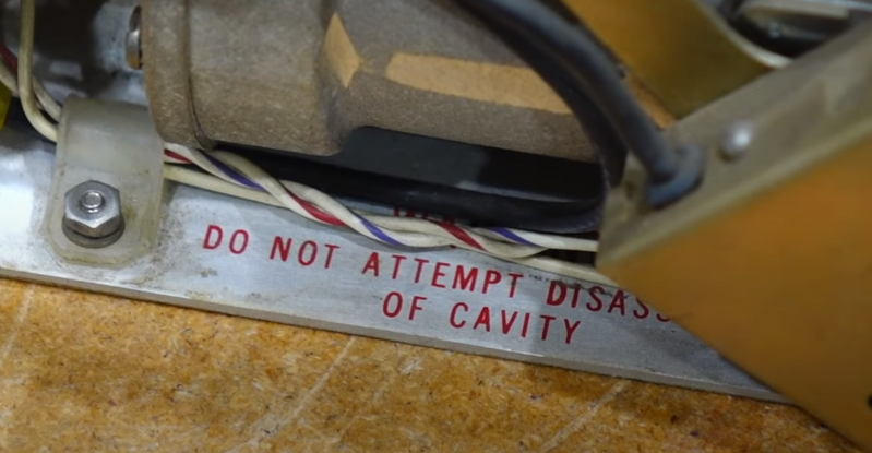
But the real beauty here is the plugin modules that gave this frequency super powers. And those modules were unfortunately manufactured with a gear grease that turned to glue after a few decades. Why does a digital frequency counter module have a clockwork component, and a metal tube with that ominous warning, “DO NOT ATTEMPT DISASSEMBLY OF CAVITY”? The tube is a resonant cavity, working as a filter. The cavity is fed with a comb generator, which generates multiple signals 10 MHz apart. The resonant filter will grab only one of the signals, giving a precise, known signal that is a power of 10 MHz. The next bit of magic in this device is a frequency mixer, which combines the test signal with this power-of-10, and outputs the difference. The resonant filter is tuned by a series of gears that move internal components. Once tuned to the nearest frequency, the difference will be less than 10Mhz, and able to be counted by the frequency counter. Just add the value shown on the dial, and you have your total frequency.
Of course, [CuriousMarc] works his magic to get things running again, not to mention doing a better job than we can explaining how the modules work. And of course, opens the forbidden fruit, and cleans that grease-turned-glue from the inner works, exploring exactly how it works, and how to get it back together. And if you want more HP 5245L goodness, maybe check out the world’s most overbuilt nixie clock.


That text is much more convincing than the “No user-serviceable parts inside” that nowadays gets plastered on anything :)
I have many devices that shorten that now to just “no serviceable parts inside” and yes, I believe that in many cases they are correct ;)
What fun is that! You have take a shot at fixing it. Sometimes you get lucky, or just learn something. Sometimes you end up with a few spare parts .
“And those modules were unfortunately manufactured with a gear grease that turned to glue after a few decades.”
Let me suggest a few drops of CLP, the stuff used to clean and lubricate rifles. Left overnight, it will dissolve even petrified grease and makes switch bushings turn smooth as butter.
It is a pity that he does not mention why the input and output coupling loops change their angle as the cavity is tuned. Of course, he might not know … yet.
Anyway, full marks for audacity!
What keeps you from telling us “why” ? :-)
Because I do not know! (I can guess, but …)
I have an inkling that it is to couple more energy into the TM mode in the lower range of the cavity. But a) I didn’t realize it then, and I’m still not 100% sure now, and b) go explain that in a 30 min video…
I hear elevator music coming our way 😃
“power of 10 Mhz” – Should that be “multiple of 10MHz?”
Comb generators make harmonics – multiples of the fundamental frequency.
https://en.m.wikipedia.org/wiki/Comb_generator
Amen brother.
And that long ago it would be multiples of 10 Mc
A cycle is a cycle. Sometimes it hertz.
I found one of these as a prop on a film set, and was sorely tempted to take it…
Probably a case where it would be better to ask for permission than forgiveness. I’d have at least asked about it.
You must have been working on the Stargate SG-1 production! Saw this counter in one episode, and whooped!
It’s fun to see how engineers worked around the decencies of electronics. My favorite was a 600 bit dynamic memory based on shock waves traveling through a block of glass.
I’m concerned that today’s engineers are not learning about these down and dirty circuit techniques. It’s easy to do it all with data converters and fast processors, but what happens when you can’t use those tools for some reason? I hold those engineers from the 60s in very high regard. Get a hold of some engineering textbooks from the 50s and ask yourself if you know engineering math to the depth they cover it.
Especially at H-P, when those initials stood for uncompromising quality and innovative design & manufacture. Pick up a copy of the H-P Journal from those years, and you’ll see that, plus credit given to the engineers who worked on those products.
We still learn a lot especially in grad level material science. Don’t worry, engineering is not in jeopardy of becoming a lost art lol.
I loved the 60s and 70s when high end gear came with real complete paper technical documentation.
Looking at the picture of the Apollo Control Room, I could swear that was the electrophysiology lab where, in the early-to-mid 1980s, I learned all about electronics and biophysics and the small signals that critters make in their cells! Everyone else called our lab “The Museum” for some reason, IDK, lol. But I remember swearing a lot at those hand me down instruments.
Still, even besides the radio stations that plagued our experiments, it was fun. Never a day without laughter.