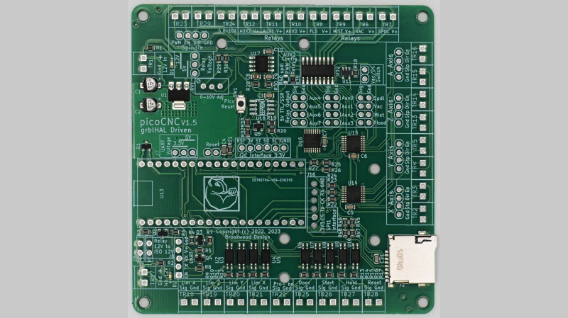
[Phil Barrett] designed a new CNC controller breakout board called the PicoCNC which uses the Raspberry Pi Pico RP2040 module and grblHAL. It packs a bunch of features typical of these controllers, and if you use the Pico W, you get WiFi connectivity along with USB. And if you don’t want connectivity, you can execute G-code directly from a micro SD card. The board is available in kit form, and schematics are posted on the GitHub repository above. Some of the features include four axes of motion, spindle control, limit switches, relay drivers, expansion headers, and opto-isolation.
This isn’t [Phil]’s first controller board. He also designed the grblHAL-based Teensy CNC controller breakout board, a step up from the usual Arduino-based modules at the time and boasting Ethernet support as well. According to the grblHAL site, nine different processors are now supported. There are well over a dozen CNC controller breakout boards listed as well. And don’t forget [bdring]’s 6-Pack grbl-ESP32 controller, a modular breakout board we covered a few years back. So pick your favorite board or roll your own and get moving.


On first sight, this project is quite similar to a Teensy breakout board:
https://hackaday.com/2020/11/11/teensy-controller-for-powerful-cncs/
Teensy can also work with Ethernet, which gives inherent extra galvanic isolation layer, which is interesting for CNC.
I also saw this RP2040 project about a week ago, and I noticed that both the step and direction pulses are managed via a 74HC595, and this is a surprising choice. When there is not enough I/O, its much more logical to put less speed critical stuff on a shift register, but I do know the RP2040 has some “special hardware”. I do wonder (but have not checked) if they put extra thought into this. A lot of the bigger stepper motor drivers use a fast optocoupler for the steps, and a much slower optocoupler for the direction, and managing timing is important here, Lots of setups have problems with step timing during direction changes.
The board appears similar to the teensy one because the same person, me, designed it.
The use of the 74AHCT595 shift register is due to several reasons: not enough pins on the Pico to drive 4 Axes and the need for 5V output logic. You are right to wonder about performance but the use of GPIO in the RP2040 allows grblHAL to have step rates of greater than 230 kHz. Since most stepper drivers have a max step rate of 200 kHz, I’d say it works rather well.
Phil, you beat me to it by two minutes ;-)
Phil prepared his reply in advance since he anticipated it :D
Oops sorry, sometimes I have some trouble with reading, or with interpreting what I read.
I guess the shift register is clocked at a few MHz, which is probably plenty fast. and the register clock of the shift register would then just give all step outputs the same (and constant) extra delay, and that is harmless. A possible hazard is what happens if a bit is updated while the shift register is still shifting. That would add a minimum delay, depending on the clock speed and latching of the shift register.
>On first sight, this project is quite similar to a Teensy breakout board
That’s because they’re both designed by the same person, as stated in the writeup.
> A lot of the bigger stepper motor drivers use a fast optocoupler for the steps, and a much slower optocoupler for the direction, and managing timing is important here, Lots of setups have problems with step timing during direction changes.
PIO (the “special hardware”) is used to shift out the data and both step pulse length and direction signal to step pulse delay are configurable in the usual Grbl fashion. In fact PIO may help to reduce jitter as interrupts that are employed by other controllers to handle pulse length and delay are no longer needed – PIO takes care of those with no processor intervention.
They call the “Special Hardware” “PIO”. It’s pretty interesting if you look it up. The examples on the github are A+.
I have trouble with laser on linux.
Is any working cad program? I have svg and how using laser on linux?
Either:
A) use the python script (dependent on having OpenSCAD installed, but you don’t need to understand OpenSCAD to use this method) “frezik laser slicer github” to take 2D slices as dxfs from a 3D STL model
or
B) import your 3d geometry in to Blender as a shape extruded from the profile you want to cut, then select the upper (or lower, but not both) perimeter lines of this shape in edit-mode, “ctrl+p” to make a new object from them. In object mode select that new object and then use Blender’s stl exporter (selecting the poly-line and TOP projection options).
Inkscape can do it too, somehow, from svg, but I much prefer using 3d modelling to design the 2d thing to proper scale then taking a dxf slice
> And if you don’t want connectivity, you can execute G-code directly from a micro SD card.
A brand new (and optional) feature ist that code running from the SD card supports both parameter (variable) access and conditional execution LinuxCNC style. This means advanced macros can be witten, stored on the SD card and executed on the controller. This includes binding such macros to tool selection (T command) and tool changes (M6 commands).
> And if you don’t want connectivity, you can execute G-code directly from a micro SD card.
A new (optional) feature is that advanced macros can be written and stored on the SD card, this includes access to parameters (variables) and conditional execution LinuxCNC style. In addition to general purpose macros callable via G65 such macros can be bound to tool selection (T command) and tool change (M6 command), making it easy for those who want to implement/control an automatic tool changer (ATC) from G-code.
I have been running Phil’s Teensy board on my CNC for a couple years now, and it has been working flawlessly. I’m sure this new board also is top notch; if I ever find a need to upgrade I will give it a shot, but the Teensy board is good enough that this need may not arise for a very long time! ;-)
Thank you Phil!
Thanks for the kind words. The teensy is the bigger brother to the Pico, faster more axes, ethernet. With the Pico, I was aiming at a board that is cost competitive to the Arduino based ones and has a LOT more features.
Looks like you succeeded;)
What license is this design based on?
Poetic?
B^)
Love always wins. Peace and CNC ;)