The huge diversity of sensors and other hardware which our community now has access to seems comprehensive, but there remain many parts which have made little impact due to cost or scarcity. It’s one of these which [Enginoor] has taken for the sensor in a 3D scanner, an industrial laser displacement sensor.
This sensor measures distance, but it’s not one of the time-of-flight sensors we’re familiar with. Instead it’s similar to a photographic rangefinder, relying on the parallax angle as seen from a sensor a distance apart from the laser. They are extremely expensive due to their high-precision construction, but happily they can be found at a more affordable level second-hand from decommissioned machinery.
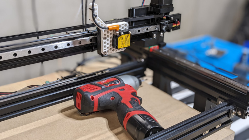
In this case the sensor is mounted on an X-Y gantry, and scans the part making individual point measurements. The sensor is interfaced to a Teensy, which in turn spits the data back to a PC for processing. By their own admission it’s not the most practical of builds, but for us that’s not the point. We hope that bringing these parts to the attention of our community might see them used in other ways.
We’ve featured huge numbers of 3D scanners over the years, including a look at how not to make one.


Maybe on a 5 axes head it could scan an object on most of its sides? Advantage is that no contact with the object is needed like with touch probes. A high resolution (sub mm) scanner for small objects of about 300x300x300mm could be really useful.
I did it with a cheap distance sensor using grbl and GRBL-Plotter: https://grbl-plotter.de/index.php?id=externalsensor&setlang=en
That one uses a time-of-flight sensor VL6180X which has a 2mm resolution at best.
The laser displacement sensor here has a resolution between 2um and 120um, so one to 3 orders of magnitude better. A non-linear varying resolution is inherent in this type of sensors.
A combination of affordability, high resolution and DIY is probably best matched with a digital dial indicator with a data output. Tradoff is that it needs physical contact, but that also makes it independent of surface color / reflectivity, etc.
Most sub-$10k 3D scanners use parallax measurement, in the form of “structured light” projected from LEDs or flash tubes rather than a laser. They don’t need advanced hardware calibration because they use a camera, so they can find the displaced light wherever it shows up and then do all the math in software; obviously the resolution is limited by the sensor, but with the cheap components you can get off the shelf now, I would think you could DIY a one-pixel 3D scanner that rivals industrial sensors for a lot less money and effort.
Indeed, plenty of DIY projects around structured light also.
https://duckduckgo.com/?q=diy+structured+light&ia=web
Affordable camera’s have a resolution of about a few thousand pixels in a row, so that would determine the dynamic range. Resolution versus distance would be dependent on lenses and such.
I guess it would be fairly easy improve the dynamic range and get sub-pixel resolution with averaging and using the readout from multiple scanlines of the sensor.
I just had a go at a price estimate of the Baumer OADM SA35 used here, and it’s around USD100 if you’re lucky to USD1300 or more.
I have made pictures with a better then 1um resolution with an EUR50 C-mount camera and a EUR60 lens. and with a decent laser pointer that can probably be used as a distance sensor with the same resolution, although depth of field becomes a serious problem quickly.
Overall there is plenty of opportunity to DIY something very nice on a small budget.
Also worth mentioning, the link below does high resolution direct measurements on the sensor, but doing calculations on reflected light is probably quite similar, just add a bit of goniometry.
https://hackaday.com/2023/03/16/laser-and-webcam-team-up-for-micron-resolution-flatness-measurements/
The cheapest scanners are just turntables for photogrammetry use, no structured light needed. Pretty much an all-software solution.
I like the idea of objective depth measurements though, and can’t help but wonder if a compromise/hybrid machine could be built to attain good resolution paired with fast scanning.
I’m thinking along the lines of a structured light scanner with very narrow FoV (minimize physical size of a pixel) that is then mechanically swept across the piece, to scan a larger object.
Yup, this is the technology used by Kinect v1. (v2 uses time-of-flight.)
For faster scan speed, you could combine kinect-style structured light with mechanical scanning, to capture more than one point at a time.
Kinect does not do structured light but TOF.
MikesElectricStuff has made some video(s) about a 2D TOF sensor I believe, and more info should be easy to find in this Weird Wide World.
The original Kinect (released for the 360 and widely used for hacking following reverse engineering of the USB data) was an IR structured light.
The later one for the XBone was ToF.
So why don’t 3D printers have 3D scanners on them?
The Germans have a fitting expression for that:
https://de.wikipedia.org/wiki/Eierlegende_Wollmilchsau
Others call it “feature creep”.
You could quite readily combine:
* Pen plotter
* 3D printer
* 3D scanner.
* Solder Paste dispenser.
* PnP machine.
* Coordinate measurement machine.
* (PCB) milling machine.
* Anything else that is XYZ based.
But the more of those features you combine, the more expensive it gets, and features are partially exclusive too. For example CNC emphasizes on rigidity and resolution and benefits from a heavy construction, while a 3D printer emphasizes more on speed while maintaining a reasonable resolution and benefits from a lightweight construction.
And there are some commercial projects with replaceable heads so they can be used for some of these tasks.
2D printers often have a 2D scanner on them. I can certainly see a future where a 3D scanner is a common feature of 3D printers.
I can’t. You need to scan the sides of your item which is a bit tricky. As per the first comment, you need 5-axis for that.
Ok you say, add something to the bed to rotate the part… and your feature creep is off & running.
There is a logical evolution of a product, sure you can shout ‘feature creep’, as many did for 2D printers as they slowly progressed from the 1980s dot matrix to a modern 3in1 printer which is fairly standard today. Right now 3D printers are effectively in the early dot matrix phase, so expect to see a lot more features of the next 20 years and it’s likely these will follow in a similar vein as 2D printers.
Note most early (and some current) 2D scanning feature require the operator to flip the paper so both sides are scanned. 3D printer/scanner could be similar, at start with.
Automatic part removal (remember when you had to manually remove paper from the printer?) will come, which may also provide the extra axis for scanning. A long with automatic filament loading/changing, and so on.
I agree that the following don’t belong with a 2D or 3D printer:
* Pen plotter
* Solder Paste dispenser.
* PnP machine.
* Coordinate measurement machine.
* (PCB) milling machine.
* Anything else that is XY[Z] based.
* Coffee maker.
But calling out some bad features doesn’t mean all new features are bad.
You do know that 3D printers aren’t really 3D, yeah? They’re really only 2D, or 2.5D at best. Like almost every other CNC machine in existence.
I’d be fascinated how you think they can be retro-fitted to scan an object in 3D. And not the “new technology bro!” you think will be happening.
Bob, first off:
> And not the “new technology bro!” you think will be happening.
I’d be fascinated to learn how HaD posters like you think dropping insults and slights will help an interaction or make HaD a better place?
> You do know that 3D printers aren’t really 3D, yeah?
That’s like of like claiming 2D printers aren’t really 2D because they print only 1 row at time (or considering the pen plotter to be the only truly 2D printer). 3D printers are definite 3D and produce real 3D objects.
> They’re really only 2D, or 2.5D at best. Like almost every other CNC machine in existence.
I understand why you say that, and sure, for things like the X-Carve and similar bench top CNC routers where you are just cutting 2D designs with a couple of Z offsets. Try to get a look at a modern commercial CNC machine in action, they are definitely 3D.
> I’d be fascinated how you think they can be retro-fitted to scan an object in 3D.
I’m not talking about retro-fitting a scanner to existing 3D printer. Although 10-20 years from now I’m sure we’ll see HaD articles on “retro-fitting the Lulzbot Taz38 scanner head to a Monoprice Makerselect i3” and such.
In away it’s kind of like saying: show me how dot matrix printers could be modified to scan documents. To make claims that future printers won’t be able to scan documents…
Anyway, I’ll give you some ideas of what the future may hold:
– First, there will always be objects that can’t be scanned 100%. For example you can’t scan the inside of a close box (this might be possible in the future, probably not for consumers in the next 2 decades).
– The scanner would possibly be a separate head (we already have tool changer 3D printers).
– The scanner would likely have multiple degrees of freedom beyond just the printer’s movement system (XYZ).
– Possibly the scanner would be attached/built-in to printer heads which have additional degrees of freedom beyond XYZ.
– Possibly the printer would scan part of the objects surface (say the top half), then 3D print a jig to the hold the scanned portion and exposing the yet-to-be-scanned bottom part for scanning. Repeat as needed.
Other factors. In the next 10-20 years we’ll see a continued increase in computing power available for things like 3D printers. Also the current state of 3D scanning is relatively nascent, we can expect to see advancements such as a smaller scanners, more accuracy, wider field of vision, etc.. So at least expect more processing power and better photogrammetry methods.
don’t forget a fermenting oven. I used my 3D printer a bunch of times to prove yeast dough and all it needs is just a gCode file and it should be housed. Then just set the temperature and time and let the dough rise. :)
Sharp has been making rangefinder sensors like these for donkey’s years. Get (for example) a GP2Y0A51SK0F at Digikey for $12 Several different ranges, update rates, output formats.
If you like your resolution to be in the cm range…
Nope. You might be thinking of the even cheaper proximity switches that depend on reflected power measurement. These were popular for wall-follower robots back in the last millennium. The rangefinder types are good for <40 microns precision for the shorter range (e.g. 15 cm) models. Actual accuracy is much worse though, so calibration needed, and it is somewhat target-dependent.
You should check out the datasheet, especially the response curve. Beam angle doesn’t get a mention, just how wide is that spot at 100mm?
I wasn’t too sure about the age of donkeys so I tried to look it up:
Molecular phylogenies indicate the most recent common ancestor of all modern equids (members of the genus Equus) lived ~5.6 (3.9–7.8) mya. Direct paleogenomic sequencing of a 700,000-year-old middle Pleistocene horse metapodial bone from Canada implies a more recent 4.07 Myr before present date for the most recent common ancestor (MRCA) within the range of 4.0 to 4.5 Myr BP.
Source:
https://en.wikipedia.org/wiki/Donkey
Well, that didn’t help much.
Rotflmao