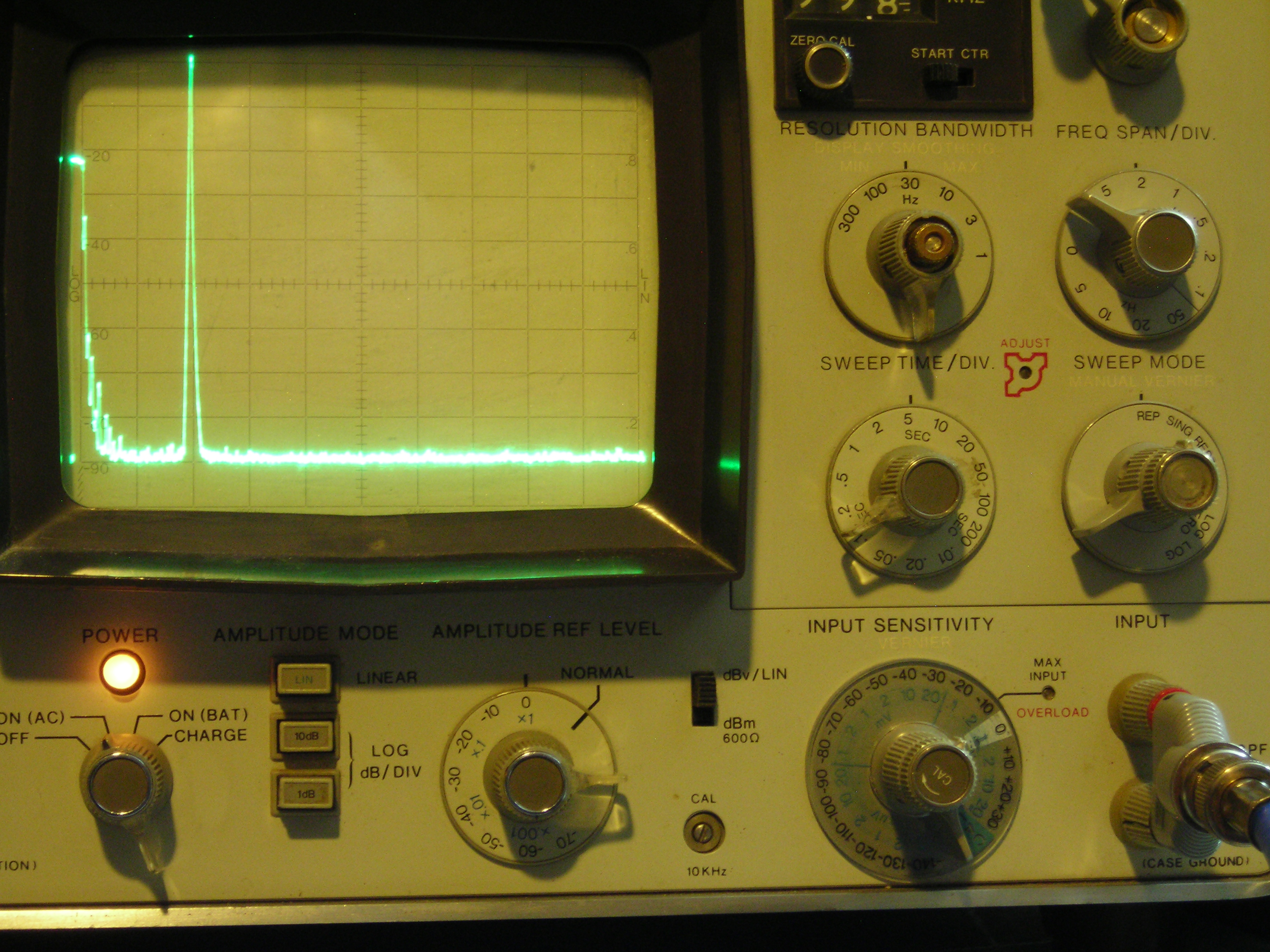
It’s not often that a single photo can tell you pretty much everything you need to know about a project, but the spectrum analyzer screenshot nearby is the perfect summary of this over-the-top low-distortion audio oscillator build. But that doesn’t mean there’s not a ton of interesting stuff going on with this one, so buckle up.
The project is by [Basin Street Design], who doesn’t really offer much by way of inspiration for this undertaking, nor a discussion on what this will be used for. But the design goals are pretty clear: build an oscillator with as little distortion as possible across the audio frequency range.
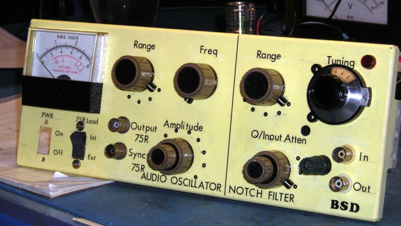
The basic circuit is the well-known Wien bridge oscillator where the R-C pairs are switched in and out of the feedback loop to achieve frequency range control. This was accomplished with rotary switches rebuilt from their original configuration in a Heathkit IG-18 sine/square wave generator, a defunct instrument that was gutted and used as an enclosure for this build. There are a lot of other treats here, too, like the automatic gain control (AGC) that uses a homebrew voltage-controlled resistor made from an incandescent lamp and a cadmium sulfide photoresistor glued inside a piece of brake line, and an output attenuator made from discrete resistors that drops the output in 10 dB steps while maintaining an overall 75-Ohm impedance.
But at the end of the day, it all comes down to that single spike on the spectrum analyzer, with no apparent harmonics. To make sure there wasn’t something hiding down in the noise, [Basin Street] added a notch filter to lower the fundamental by 60 dB, allowing the spectrum analyzer sensitivity to be cranked way up. Harmonics were visible, but so far down into the noise — as low as -115 dBc — that it’s hardly worth mentioning.
There’s a lot more detail in this one, so dive in and enjoy. If you want another take on Wien bridge circuits, check out this recent LM386-based oscillator. Just don’t expect such low distortion with that one.


< -115dB is damn impressive. Thanks for the post.
At first glance I thought that peak on the spec an was the 0Hz spike. Seeing it as an actual signal was kinda spooky – I think that’s the cleanest spectrum I’ve ever seen. On a side note, that (HP?) analyzer seems to have some pretty impressive specs too.
Reading about the light-coupled voltage controlled resistor brought back a 45-year-old memory of using an LED, an LASCR, and tube cut from a BIC pen barrel lined with aluminum foil to create a thyristor-based opto-coupler for a light organ my partner and I used for DJ’ing gigs. God I’m old…
Thanks for the article! I love digital electronics, but I still find analog warmer and closer to my heart…
Very pure sine waves are freaky to listen to, since they reveal exactly where your hearing loss is. The brain is brilliant at inferring missing tones from their harmonic frequencies, which is what modern sound systems use to fake around the lack of proper mid/bass speakers.
They also mess with your head and often it is hard to locate where they are coming from. Stereo location is hard because, I think and correct me if I’m wrong, higher audio frequencies have a wavelength about the width of your head so they are in phase or nearly in phase even when not right in front of you.
1 kHz wavelength is about the distance between your ears. Above that, you get the kind of “aliasing error” you’re referring to – but of course the brain is smarter than that. It also takes differences in amplitude into account, and the shape of the ear is such that it causes reflections and delays depending on the direction of the sound – because at higher frequencies the sound becomes more directional like a light beam. If the sound is coming in from the side, the other ear won’t hear much of it anyways.
That’s also why virtual 3D sound is so difficult to pull off. Your brain has learned how your particular ears change the sounds coming from different distances and directions, and listening to sounds on headphones messes with that.
I used a square wave when I lost a wireless earbud; it was the easiest to hear of the loud tones I could generate. Something between 500 and 2kHz probably. A lot of locating sounds can be from logic on the relative sense of different frequency components.
I used to repair and calibrate audiometric equipment so I hear you – pun intended…
The incandescent gain limiter has been a fundamental part of these circuits since their inception. Of course, they just used one with a specific transfer function to limit gain on its own rather than trying to couple it to anything else.
HP’s first product (a wein bridge sine wave generator), had that configuration.
Years ago (70’s ?) there was an article on how to modify another Heath oscillator – the IG-18.
Similar final results to this. It still sits on my bench.
Look up IG-18 low distortion on the ‘net. Lots of articles and pcboards.
Thanks! I’m not likely to find an actual Heathkit unit any time soon, but I’ve found schematics and plan to start collecting parts to build one.
This is very good performance for an oscillator usable across the entire audio band. About a year ago I did an internet search and found at least one design good for 1 PPM distortion, but only for a single frequency.
I do worry about the long term stability of CdS cells. Perhaps the gluing it inside brake tubing provides sufficient protection from environmental degradation.