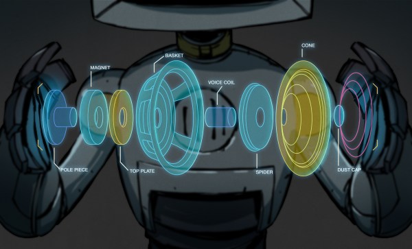
In previous episodes of this long-running series looking at the world of high-quality audio, at every point we’ve stayed in the real world of physical audio hardware. From the human ear to the loudspeaker, from the DAC to measuring distortion, this is all stuff that can happen on your bench or in your Hi-Fi rack.
We’re now going for the first time to diverge from the practical world of hardware into the theoretical world of mathematics, as we consider a very contentious topic in the world of audio. We live in a world in which it is now normal for audio to have some form of digital compression applied to it, some of which has an effect on what is played back through our speakers and headphones. When a compression algorithm changes what we hear, it’s distortion in audio terms, but how much is it distorted and how do we even measure that? It’s time to dive in and play with some audio files. Continue reading “Know Audio: Lossy Compression Algorithms And Distortion”→
It’s been a while since the last installment in our Know Audio series, in which we investigated distortion as it applies to Hi-Fi audio. Now it’s time to return with part two of our look at distortion, and attempt some real-world distortion measurements on the bench.
Last time, we examined distortion from a theoretical perspective, as the introduction of unwanted harmonics as a result of non-linearities in the signal path. Sometimes that’s a desired result, as with a guitar pedal, but in a Hi-Fi system where the intention is to reproduce as faithfully as possible a piece of music from a recording, the aim is to make any signal path components as linear as possible. When we measure the distortion, usually expressed as THD, for Total Harmonic Distortion, of a piece of equipment we are measuring the ratio of those unwanted harmonics in the output to the frequencies we want, and the resulting figure is commonly expressed in dB, or as a percentage. Continue reading “Know Audio: Distortion Part Two”→
If your guitar needs more distortion, lower audio fidelity, or another musical effect, you can always shell out some money to get a dedicated piece of hardware. For a less conventional route, though, you could follow [Brek Martin]’s example and reprogram a handheld game console as a digital effects processor.
[Brek] started with a Sony PSP 3000 handheld, with which he had some prior programming experience, having previously written a GPS maps program and an audio recorder for it. The PSP has a microphone input as part of the connector for a headset and remote, though [Brek] found that a Sony remote’s PCB had to be plugged in before the PSP would recognize the microphone. To make things a bit easier to work with, he made a circuit board that connected the remote’s hardware to a microphone jack and an output plug.
[Brek] implemented three effects: a flanger, bitcrusher, and crossover distortion. Crossover distortion distorts the signal as it crosses zero, the bitcrusher reduces sample rate to make the signal choppier, and the flanger mixes the current signal with its variably-delayed copy. [Brek] would have liked to implement more effects, but the program’s lag would have made it impractical. He notes that the program could run more quickly if there were a way to reduce the sample chunk size from 1024 samples, but if there is a way to do so, he has yet to find it.
If you’d like a more dedicated digital audio processor, you can also build one, perhaps using some techniques to reduce lag.
Distorted guitars were a big part of the rock revolution last century; we try to forget about the roll. As a youth, [David Hilowitz] couldn’t afford a loud aggressive amp, a distortion pedal, or even a proper electric guitar. This experience ended up teaching him that you can use random old audio hardware as a distortion effect.
[David’s] guitar journey started when he found a classical guitar on a dumpster. He learned to play, but longed for the sound of a proper electric guitar. Family friends gifted him a solitary pickup, intending he build a guitar, but he simply duct-taped it to his steel-strung classical instead. The only thing he lacked was an amp. He made do with an old stereo system and a record pre-amp. With his his faux-electric guitar plugged into the microphone input, he was blessed with a rudimentary but pleasant distortion that filled his heart with joy.
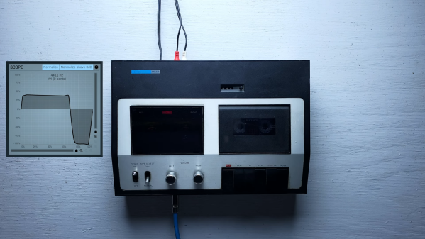
[David] goes on to explain the concepts behind distorted guitar sounds, and how his home hi-fi was able to serve as a passable starter amp when he was young and couldn’t afford better. He then goes on the hunt for more old gear at a local Goodwill store, finding a neat old tape deck that similarly produced some nice warm distorted tones. In [David’s] experience, old hi-fi gear with microphone inputs can generally do a decent job in this role, with electric guitar pickups typically overloading the preamps which expect a lower-level signal. It’s different to what you’d get from a Big Muff or Boss DS-1, but it’s a neat sound nonetheless.
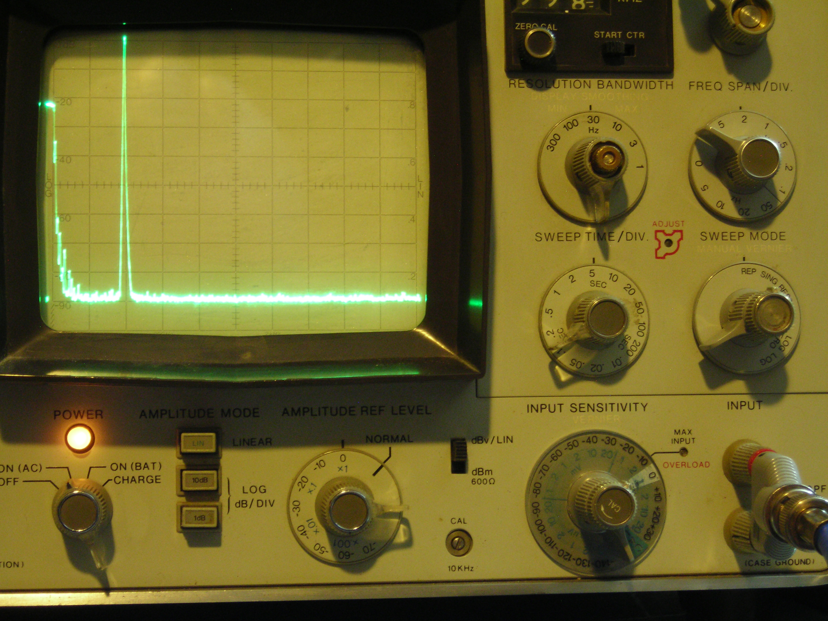
It’s not often that a single photo can tell you pretty much everything you need to know about a project, but the spectrum analyzer screenshot nearby is the perfect summary of this over-the-top low-distortion audio oscillator build. But that doesn’t mean there’s not a ton of interesting stuff going on with this one, so buckle up.
One spike at the fundamental and not much more.
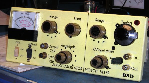
The project is by [Basin Street Design], who doesn’t really offer much by way of inspiration for this undertaking, nor a discussion on what this will be used for. But the design goals are pretty clear: build an oscillator with as little distortion as possible across the audio frequency range.
The basic circuit is the well-known Wien bridge oscillator where the R-C pairs are switched in and out of the feedback loop to achieve frequency range control. This was accomplished with rotary switches rebuilt from their original configuration in a Heathkit IG-18 sine/square wave generator, a defunct instrument that was gutted and used as an enclosure for this build. There are a lot of other treats here, too, like the automatic gain control (AGC) that uses a homebrew voltage-controlled resistor made from an incandescent lamp and a cadmium sulfide photoresistor glued inside a piece of brake line, and an output attenuator made from discrete resistors that drops the output in 10 dB steps while maintaining an overall 75-Ohm impedance.
But at the end of the day, it all comes down to that single spike on the spectrum analyzer, with no apparent harmonics. To make sure there wasn’t something hiding down in the noise, [Basin Street] added a notch filter to lower the fundamental by 60 dB, allowing the spectrum analyzer sensitivity to be cranked way up. Harmonics were visible, but so far down into the noise — as low as -115 dBc — that it’s hardly worth mentioning.
There’s a lot more detail in this one, so dive in and enjoy. If you want another take on Wien bridge circuits, check out this recent LM386-based oscillator. Just don’t expect such low distortion with that one.
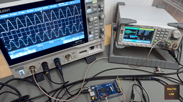
Guitarists will do just about anything to get just the right sound out of their setup, including purposely introducing all manner of distortion into the signal. It seems counter-intuitive, but it works, at least when it’s done right. But what exactly is going on with the signal? And is there a way to simulate it? Of course there is, and all it takes is a little math and some Arduino code.
Now, there are a lot of different techniques for modifying the signal from an electric guitar, but perhaps the simplest is the humble diode clipping circuit. It just uses an op-amp with antiparallel diodes either in series in the feedback loop or shunting the output to ground. The diodes clip the tops and bottoms off of the sine waves, turning them into something closer to a square wave, adding those extra harmonics that really fatten the sound. It’s a simple hack that’s easy to implement in hardware, enough so that distortion pedals galore are commercially available.
In the video below, [Sebastian] explains that this distortion is also pretty easy to reproduce algorithmically. He breaks down the math behind this, which is actually pretty approachable — a step function with a linear part, a quadratic section, and a hard-clipping function. He also derives a second, natural exponent step function from the Schockley diode equation that is less computationally demanding. To implement these models, [Sebastian] chose an Arduino GIGA R1 WiFi, using an ADC to digitize the guitar signal and devoting a DAC to each of the two algorithms. Each distortion effect has its own charms; we prefer the harsher step function over the exponential algorithm, but different strokes.
Kudos to [Sebastian] for this easy-to-understand treatment of what could otherwise be a difficult subject to digest. We didn’t really expect that a guitar distortion pedal would lead down the rabbit hole to diode theory and digital signal processing, but we’re glad it did.
If you follow audiophile reviewers, you’ll know that their stock-in trade is a very fancy way of saying absolutely nothing of quantifiable substance about the subject while sounding knowledgeable about imagined differences between devices that are all of superlative quality anyway. If you follow us, we’ll tell you that the only reviews that matter are real-world measurements of audio performance, and blind listening tests. We don’t have to tell you how to listen to music, but perhaps it’s time in our Know Audio series to look at how audio performance is measured.
Before reaching for the bench, it’s first necessary to ask just what we are measuring. What are the properties which matter in an audio chain, or in other words, just what is it that makes an audio device good?