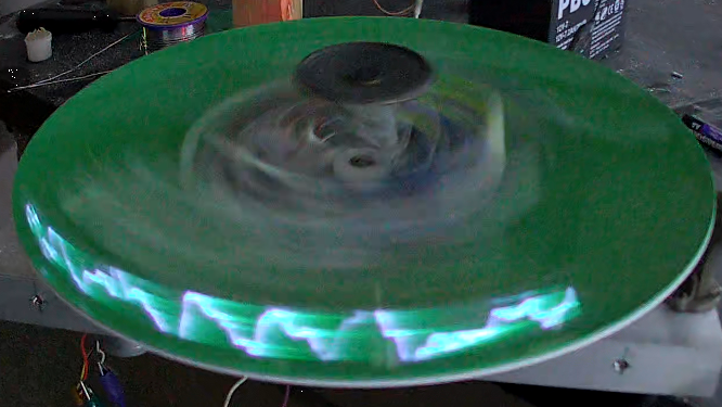
A question for you: if the cathode ray tube had never been invented, what would an oscilloscope look like? We’re not sure ourselves, but it seems like something similar to this mechanical tachyscope display might worked, at least up to a point.
What’s ironic about this scenario is that the tachyscope [Daniel Ross] built actually uses a CRT from a defunct camcorder viewfinder as the light-up bit of what amounts to a large POV display. The CRT’s horizontal coil is disconnected while the vertical coil is attached to the output of a TEA205B audio amplifier. The CRT, its drive electronics, and the amp are mounted to a motorized plastic platter along with a wireless baby monitor, to send audio to the CRT without the need for slip rings — although a Bluetooth module appears to be used for that job in the video below.
Speaking of slip rings, you’d expect one to make an appearance here to transfer power to the platter. [Daniel] used a slip ring for his previous steampunk tachyscope, but this time out he chose a hand-wound air core transformer, with a stationary primary coil and secondary coil mounted on the platter. With a MOSFET exciter on the primary and a bridge rectifier on the secondary, he’s able to get the 12 volts needed to power everything on the platform.
Like most POV displays, this one probably looks better in person than it does in video. But it’s still pretty cool, with the audio waveforms sort of floating in midair as the CRT whizzes around. [Daniel] obviously put a lot of work into this, not least with the balancing necessary to get this running smoothly, so hats off for the effort.


“A question for you: if the cathode ray tube had never been invented, what would an oscilloscope look like?”
Like a mechanical oscillograph?
Here in ol’ Germany, we used to casually call the oscilloscope an oscillograph.
That’s because the CRT screen is being “written” to, by the beam.
And that’s not too different to its mechanical predecessor.
Mechanical oscillographs with pens and papers do serve the same basic principle of drawing lines, they’re just meant for slower applications (EEG/EKG, seismic activity etc).
I came here to mention oscillograph.
You did a better job!
Another possibility is electro-mechanically tilting a mirror to deflect a light beam.
Yeah, there even were actual implementations where a photographic slide was dropped to capture faster waveforms (see https://en.wikipedia.org/wiki/History_of_the_oscilloscope ). It’s good up to 10 kHz with a fast galvanometer.
Early portable ECG equipment used a mirror galvanometer to “write” on 35mm film or direct-print paper (similar to Kodak Linagraph paper).
In answer to the first question, a pre-CRT oscilloscope looked like a spinning mirror and a manometric flame.
https://en.wikipedia.org/wiki/Koenig%27s_manometric_flame_apparatus
It would have used a Nipkow Disc, the same way television started.
The TV repair shop where I worked as a kid had an oscilloscope with no CRT. It had a spinning mirror to create the horizontal sweep, and a bar-graph vacuum tube to produce the vertical sweep. The waveforms it displayed were “filled in” under the line.
Very neat, especially the air-core transformer power coupling, but that tube looks way overdriven and worse, with only a vertical line trace and no horizontal drive. I wonder how long the phosphors will last.