One of the first things everyone does when they get a video camera is to point it at the screen displaying the image, creating video feedback. It’s a fascinating process where the delay from image capture to display establishes a feedback loop that amplifies the image noise into fractal patterns. This sculpture, modestly called The God Machine II takes it to the next level, though.
We covered the first version of this machine in a previous post, but the creator [Dave Blair] has done a huge amount of work on the device since that allows him to tweak and customize the output that the device produces. His new version is quite remarkable, allowing him to create intricate fractals that writhe and change like living things.
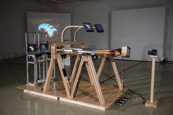
The God Machine II is a sophisticated build with three cameras, five HD monitors, three Roland video switchers, two viewing monitors, two sheets of beam splitter glass, and a video input. This setup means it can take an external video input, capture it, and use it as the source for video feedback, then tweak the evolution of the resulting fractal image, repeatedly feeding it back into itself. The system can also control the settings for the monitor, which further changes the feedback as it evolves. [Blair] refers to this as “trapping the images.”
The exciting thing here is that this is an analog process. Although he is using HD digital cameras, all of the evolution happens from the analog feedback process of capturing an image, then displaying it and capturing it again.
The whole thing is built in a walnut frame that synchronizes the cameras and screens to keep the images in the feedback loop. In his Tumblr of the build process, there is more detail, where [Dave] shows how the device evolved into its current state over the years.


In the 1960’s in the USA public broadcasting from vocation schools played hours of this stuff. Frequently. It was made by students playing with the TV cameras and monitors who thought they had discovered a new art form.
I am guilty of pointing my first video camera at the TV and watching it freak out. That was back in the 80’s. I still remember my mother telling me to stop before I break the TV. With the tube style TV’s of the time it tended to flash back forth between black and white with many colors in between.
I started making video feedback in 1987 at UCSC with CRT TVs. It’s the fine control of the brightness/contrast/hue/saturation knobs that keeps the image somewhere between all white and all black – as you describe – the Middlespace, where the magic happens.
In my project featured in this article, I use special high definition monitors that have these control knobs, creating HD video feedback in a way not possible with traditional HD televisions.
Dave (The Light Herder)
Dave, this is really inspiring stuff! So many of us have probably contemplated building something like this, who knew you could take it so far. Thank you so much for sharing this.
Side to side was fun, but nothing beats the twist. It goes on forever.
That is pretty cool.
Seems like it is ripe for some AI amplification?
Absolutely not.
I had always wondered if IFS-type fractals could be produced this way and had thought a lot about doing it. Nice to see someone actually doing it. The actual math behind IFS fractals is (like most fractals) incredibly simple, and just full of really cool effects that cause from tiny differences being amplified exponentially.
It was already featured here a few years back: https://hackaday.com/2021/07/28/video-feedback-effects-make-a-glorious-spectacle-in-hd/
There have been significant changes since then. The device now has two monitor structures. A feedback loop between each monitor structure and its camera occurs, plus a feedback loop between the monitor structures themselves is now possible, creating an entirely new level of intricacy.
For instance, in the videos featured in this article, the fractal on the right side of the screen is created by the fractal on the left side of the screen, and vice versa – they create each other, which is kind of crazy. crazy.
The device is also completely rebuilt out of Maple and Mahogany, and as much more fancy😏